[0003] Capacitive sensors are often employed to sense a measured input (e.g., acceleration, velocity, position) and provide a capacitive output that is representative of the input. In operation, such sensors include one or more capacitors whose capacitance varies in response to changes in the value of the measured input. These variable capacitors can be employed in measurement circuitry that translates the capacitance value or values into a corresponding value of the measured input. Often, however, a non-
linear relationship exists between the change in capacitance and the measured input. Because non-
linearity creates disadvantageous effects (e.g., by intorducing
distortion into the output of the measurement circuitry), it is desirable to reduce or eliminate the non-
linearity introduced into the measurement by the variable capacitance.
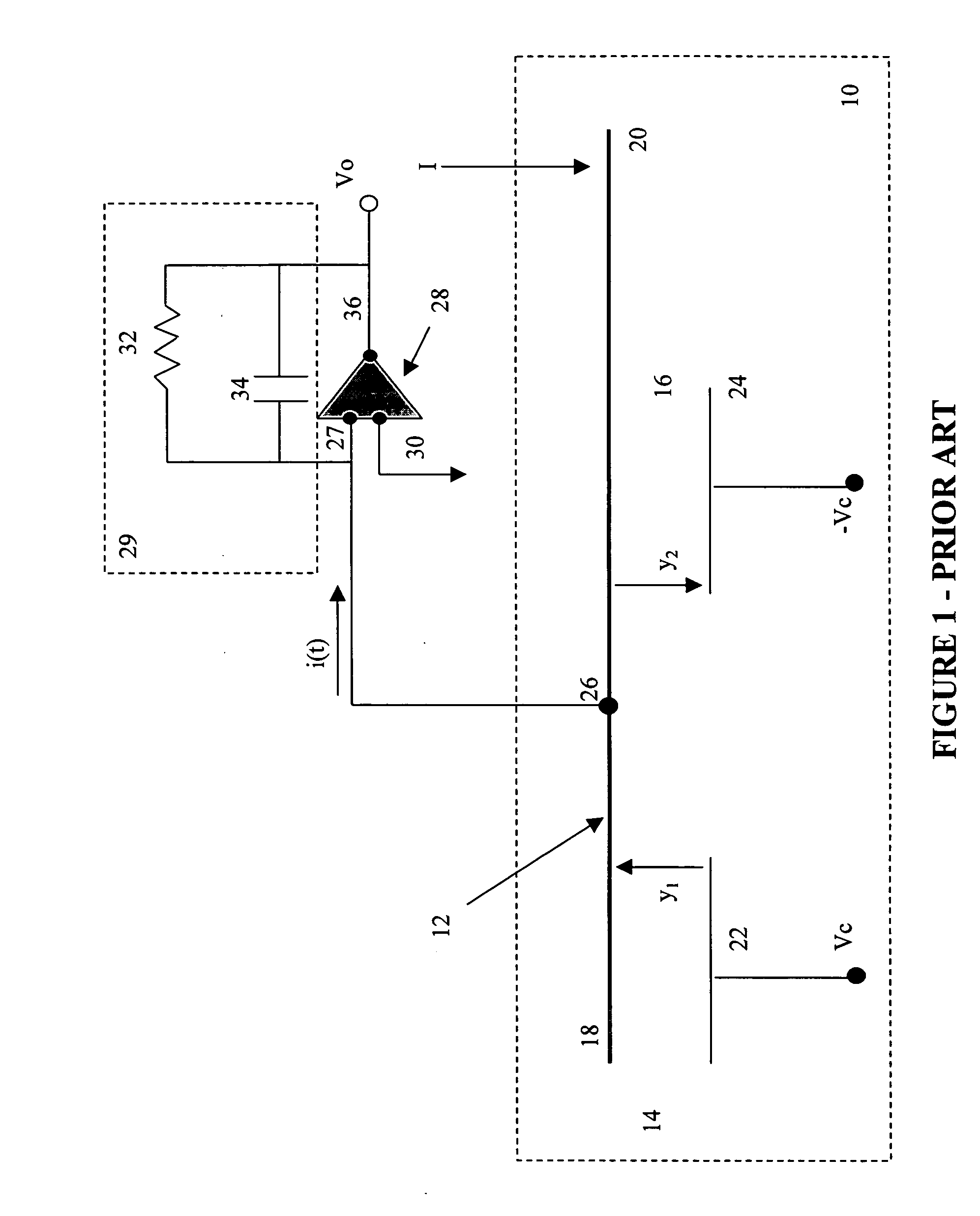
[0004] For example, FIG. 1 shows a prior art circuit employing a micro electro-
mechanical system (“MEMS”) to sense acceleration. The MEMS includes a sensor 10 configured in a differential capacitive bridge. The sensor 10 includes a
proof mass 12, a first capacitor 14, and a second capacitor 16. A left side 18 of the
proof mass 12 provides a moveable electrode for the first capacitor 14. A right side 20 of the
proof mass 12 provides a moveable electrode for the second capacitor 16. Each of the first capacitor 14 and the second capacitor 16 include a fixed electrode 22 and 24, respectively. The fixed electrode 22 is connected to a positive supply
voltage Vc, and the fixed electrode 24 is connected to a negative supply
voltage −Vc. A connection point 26 of the proof
mass 12 is connected to a first input terminal 27 of an
amplifier 28 to supply a
signal Vo responsive to a measured input I. A second input terminal 30 of the amplifier 28 is connected to ground. A feedback
resistor 32 and a
fixed capacitor 34 are connected between an output terminal 36 of the amplifier 28 and the first input terminal 27, i.e., in a feedback circuit 29 of the amplifier 28. The output
voltage Vo, is supplied by the amplifier at the output terminal 36.
[0005] The gap of capacitor 14 is represented by y1 and the gap of capacitor 16 is represented by y2. A nominal gap (for example, the gap when the measured input is zero) occurs when the proof
mass 12 is in a null position. In operation, the measured input (acceleration) acts on the right side 20 of the proof
mass 12. In response to the acceleration, the proof mass 12 pivots about the connection point 26. For example, where positive acceleration is in the downward direction at the right side 20 of the proof mass 12, a positive acceleration will cause gap y1 to increase and gap y2 to decrease as shown by the arrows associated with each capacitor 14, 16. Because capacitance is determined, in part, by the gap between the electrodes of the capacitor, the capacitances of both capacitors 14, 16 change as the corresponding gap changes (i.e., an increase in the gap decreases the capacitance). Further, the voltage that is supplied to the first input terminal also varies as the capacitances of capacitors 14, 16 change. For example, when the proof mass 12 is in the null position the gap y1 equals the gap y2. As a result the signal appearing at the connection point 26, and output voltage V0 both equal zero. However, as the proof mass 12 rotates about the connection point 26, the difference in the capacitance of the first capacitor 14 and the capacitance of the second capacitor 16 result in a non-zero output voltage V0 being generated at the output terminal 36 of the amplifier 28.
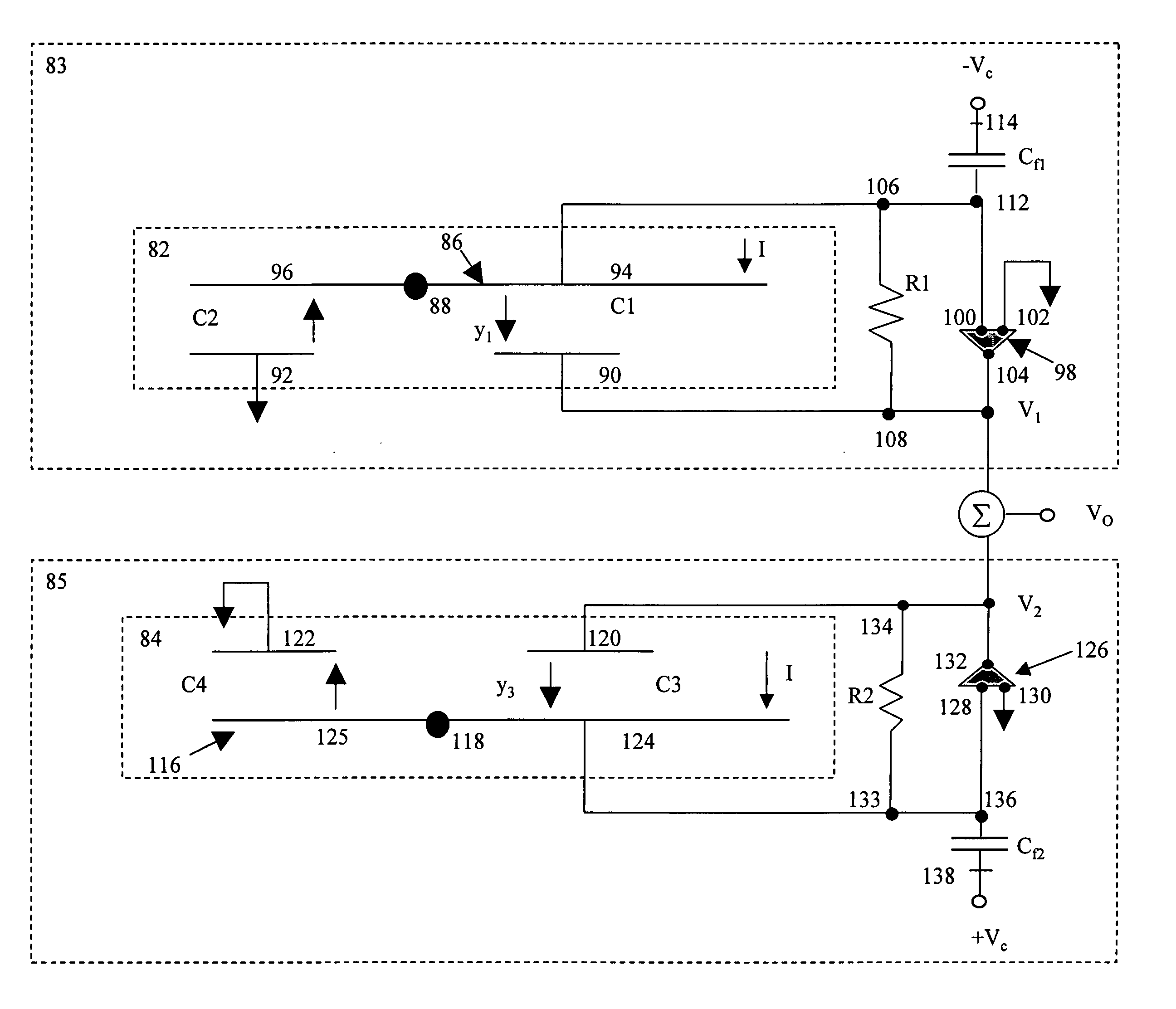
[0006] As is shown by Equation 1, the output voltage V0 of the circuit in FIG. 1 is non-linear because V0 is proportional to the capacitance which varies inversely with changes in the gap between the electrodes. Vo=-vECf[Δ C0-Σ C0y0y+Δ C0y02y2-Σ C0y03y3+Δ C0y04y4-…](1) In Equation 1, the term y0 represents the nominal gap, i.e., the gap between electrodes when the proof mass 12 is in the null position. The term ΔC0 represents the difference between the capacitances of capacitor 14 and capacitor 16 when the proof mass is in the null position. Generally, this difference is due to manufacturing tolerances found in the fabrication of the sensor 10. Cf is the capacitance of the
fixed capacitor 32. The term Σ C0 represents the sum of the capacitance of capacitor 14 and the capacitance of capacitor 16 when the proof mass 12 is in the null position. The non-linearity is introduced by the terms that are raised to a power greater than one (i.e., y2, y3). These are dependent on the change in the gap (represented by y) when the proof mass 12 is moved from the null position.
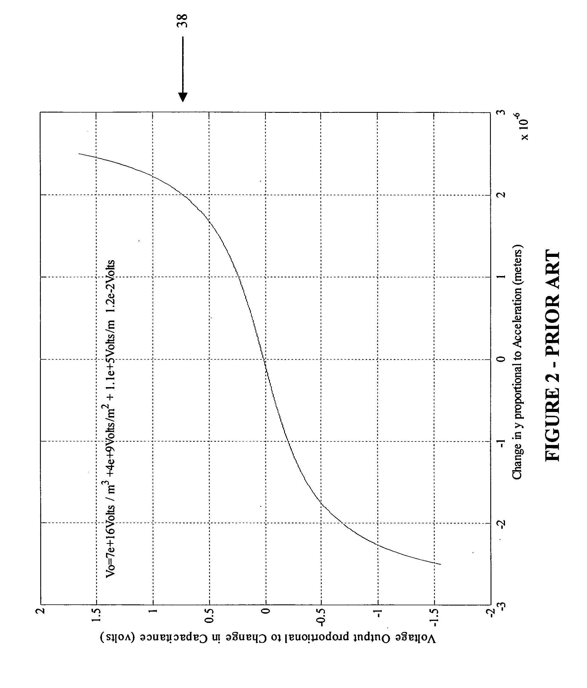
[0007] The non-linearity is shown in FIG. 2 where V0 varies non-linearly in relation to the change in the gap y. In FIG. 2, the y-axis represents the output voltage V0 and the x-axis represents the change in the gap y in response to the measured input.
[0008] One approach to dealing with the non-linear response of the circuitry has been to employ a force rebalance loop. Such an approach is also referred to as employing a
closed loop architecture. A force rebalance loop applies a signal to the sensor to counteract the affects of the measured input and maintain the proof mass 26 in the null position. The calculated value of the measured input is derived from the signal that is required to maintain the proof mass 26 in the null position. However, force rebalance loops are problematic because they add a substantial degree of complexity to both the design of the sensor and the design of the
electronic circuit. As a result, closed loop architecture is more difficult to produce, requires additional area in the
integrated circuit, and dissipates more power. Additional disadvantages of closed loop architecture include limited bandwidth and poor performance in an environment that includes vibration such as those that are often encountered in applications where capacitive sensors are employed. SUMMARY OF THE INVENTION

