Heat-sink with large fins-to-air contact area

a heatsink and finstoair technology, which is applied in the direction of cooling/ventilation/heating modification, electrical equipment, lighting and heating apparatus, etc., can solve the problems of high-power components such as microprocessors, which cannot economically be cooled by a cooling device, damage to the pcb and the processor, and the pressure, which can be developed by such an embedded fan, etc., to achieve minimal axial thickness, reduce the distance between adjacent pcbs

Inactive Publication Date: 2005-07-07
EREL DAVID
View PDF17 Cites 59 Cited by
  • Summary
  • Abstract
  • Description
  • Claims
  • Application Information

AI Technical Summary

Benefits of technology

[0010] Accordingly, it is a principal object of the present invention to overcome the above disadvantages and drawbacks of the prior art by providing a cooling device with high cooling capac

Problems solved by technology

Modern, high-power components, such as microprocessors, cannot economically be cooled by a cooling device that utilizes the circulated forced air which cools the cabinet if the power of the fan and the generated noise is to be maintained at reasonable levels.
This can lead to the cooling device inadvertently causing damage to the PCB

Method used


Image

  • Heat-sink with large fins-to-air contact area
  • Heat-sink with large fins-to-air contact area
  • Heat-sink with large fins-to-air contact area

Examples


Embodiment Construction

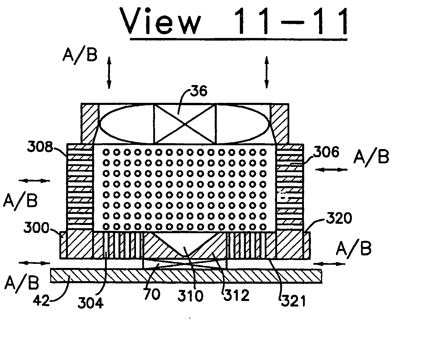
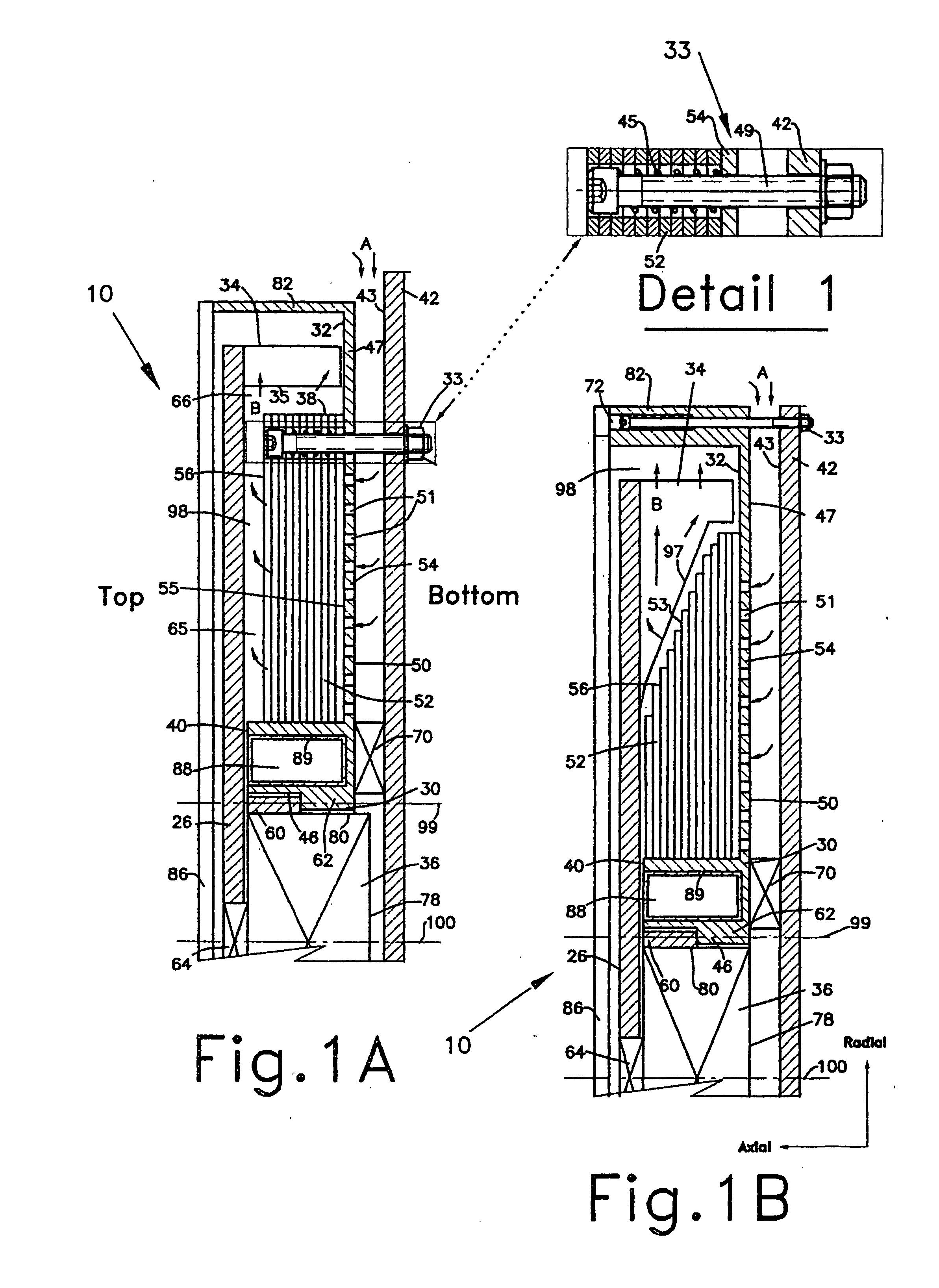
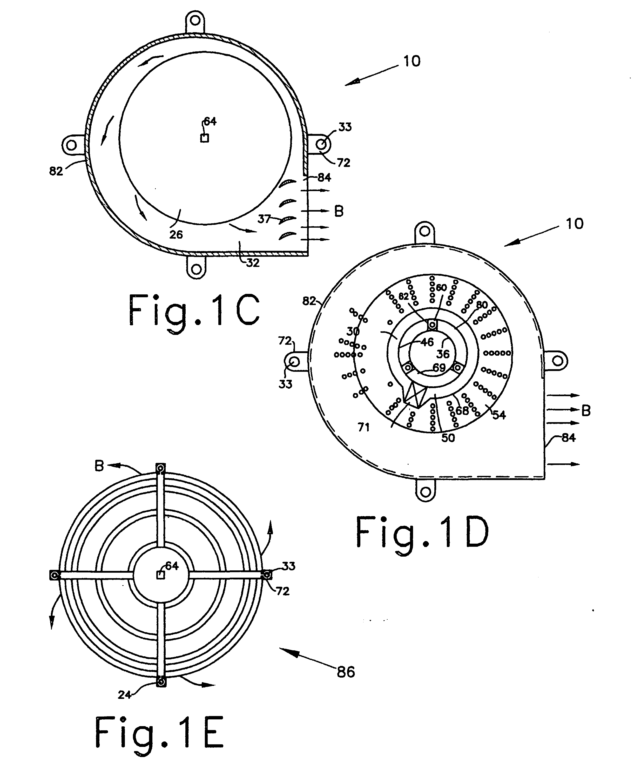
[0060] With current technology, mass manufacturing of a heat-sink of up to 40 mm axial height, densely populated by through-perforations of less than 12 mm-square footprint area, is most economical by utilizing any of the combination of stacked perforated and / or indented plates hereinafter described. Notwithstanding, the present invention is not limited to embodiments composed of stacked perforated and / or indented plates, but, can be made of any commonly used material as is known to those skilled in the art. For example, a heat-sink may be made of a solid and relatively thick perforated graphite block, wherein due to the softness of the material, it can be densely perforated or fine-blanked by utilizing currently available high output perforating or fine-blanking processes.

[0061] Extruded perforated tubing can also be considered, providing the perforations are sufficiently small to provide the equal surface area as in the perforated stacked plates of a preferred embodiment of the i...


PUM


Abstract

A heat sink adapted for cooling a heat generating component, operative with an air moving means to generate airflow and remove the generated heat. The heat sink comprises a heat conducting element in thermal contact with the heat generating component, which is also in thermal contact with a plurality of fins having through fin-perforations defining free airflow passages and heat paths so as to spread the generated heat through the perforated fins. The structural configuration and relative spatial disposition of the perforated fins form airflow directing elements for the generated airflow, which flows via an air inlet and through inflow and outflow air passages which are in fluid communication via the fin-perforations, such that the airflow directing elements at least partially block the generated airflow, thus substantially directing all of it to flow via each of the fin-perforations, thereby developing cross-flow only once through the fin-perforations so as to exit via the air outlet.

Description

FIELD OF THE INVENTION [0001] The present invention generally relates to cooling devices for cooling electrical components, and more particularly, to a low-profile heat-sink with large fins-to-air contact area and a fan element, suitable for forced airflow, active cooling of electronic components disposed on densely packed printed circuit boards. BACKGROUND OF THE INVENTION [0002] The present invention is a continuation of prior, US Provisional Patent Applications: 60 / 352 252, dated Jan. 30, 2002; 60 / 374 798, dated Feb. 24, 2002; and 60 / 394 513 dated Oct. 7, 2002 filed by the named sole inventor, David Erel, and which assume the protection of the respective dates of filing for the inventive concepts and preferred embodiments described in their respective prior Provisional Patent Applications and which are reintroduced hereinbelow. [0003] Electronic cabinets, such as used in the computer industry, commonly comprise a plurality of double-sided, printed circuit boards (PCBs) supporting...

Claims


Application Information

Patent Timeline
IPC IPC(8): H01L23/36H05K7/20H01L23/467
CPCH01L23/467H01L2924/0002H01L2924/00
Inventor EREL, DAVID
Owner EREL DAVID
Why Eureka
Try Eureka