
Method and apparatus for energy efficient particle-size reduction of particulate material

Inactive Publication Date: 2005-07-07
EASTMAN KODAK CO
View PDF2 Cites 13 Cited by
  • Summary
  • Abstract
  • Description
  • Claims
  • Application Information

AI Technical Summary

Benefits of technology

[0009] An advantage of the present invention is that a desired particle size is obtained with reduced input energy relative to a conventional single-stage particle-size reduction process.
[0010] Yet another advantage of the present invention is that for a fixed input energy smaller particle sizes are obtained relative to a conventional single-stage particle-size reduction process.

Problems solved by technology

The ability to reduce particle size is limited by various factors, including the fracture mechanics of the binder resin, which, in turn, is affected by the dispersion of the other ingredients within the toner and the adhesion thereof to the binder resin.
The ability to reduce toner particle size is further limited by the inherent toughness of the toner binder.
Thus, for a given or maximum amount of input energy, a particle size reduction process is limited to producing particles having a certain minimum average particle size.

Method used


Image

  • Method and apparatus for energy efficient particle-size reduction of particulate material
  • Method and apparatus for energy efficient particle-size reduction of particulate material
  • Method and apparatus for energy efficient particle-size reduction of particulate material

Examples


example 2

[0038] A first black toner extrudate was prepared by melt blending Regal 330 carbon black pigment from Cabot Corporation, Billerica, Mass. USA in a 30 mm twin-screw extruder with Binder C polyester of Kao Corporation of Tokyo, Japan, and with 2 pph Bontron E-84 charge agent such that the final pigment concentration was 3.0 parts of pigment per 100 parts resin by weight. These concentrations were chosen, for specific colorimetric properties not pertinent to the invention. The two toner extrudates were each individually cooled out of the extruder through a chill-belt, and granulated. The resultant toner extrudate granules were of approximately 500 microns in size.

[0039] The first black toner extrudate was pulverized and classified to the desired volume-average particle size of from approximately 7.5μ to approximately 8.0μ. Similarly, a second black toner extrudate was prepared using methods identical to the above-described methods, but having a higher pigment concentration of 4.5 par...

example 3

[0046] A magenta toner extrudate was prepared by melt blending a pigment flush obtained from BASF Aktiengesellschaft of Ludwigshafen, Germany, as Lupreton Red 1255 in a 30 mm twin-screw extruder with Binder C polyester of Kao Corporation of Tokyo, Japan, and with 2 pph Bontron E-84 charge agent such that the final pigment concentration was 6.0 parts of pigment per 100 parts resin by weight. These concentrations were chosen, for specific colorimetric properties not pertinent to the invention. The toner extrudate was cooled out of the extruder through a chill-belt, and granulated. The resultant toner granules were of approximately 500μ in size.

[0047] Two separate batches T1 and T2 of the magenta toner extrudate were pulverized to respective volume-average particle sizes using a conventional single-stage process. More particularly, batch T1 of magenta toner material was pulverized in a single-stage process to a final or desired volume-average particle size of approximately 6.0μ. A sec...


PUM


Abstract

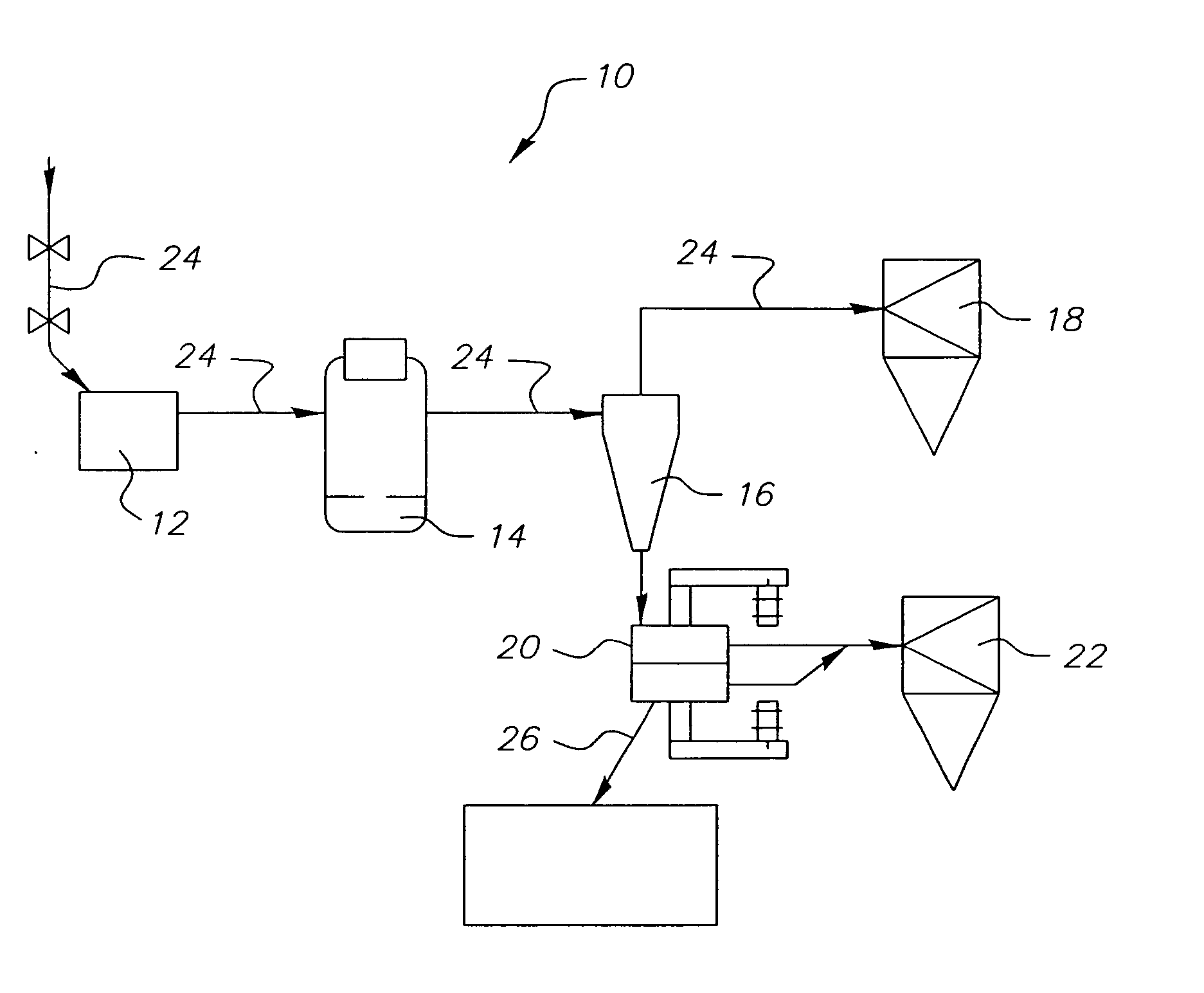
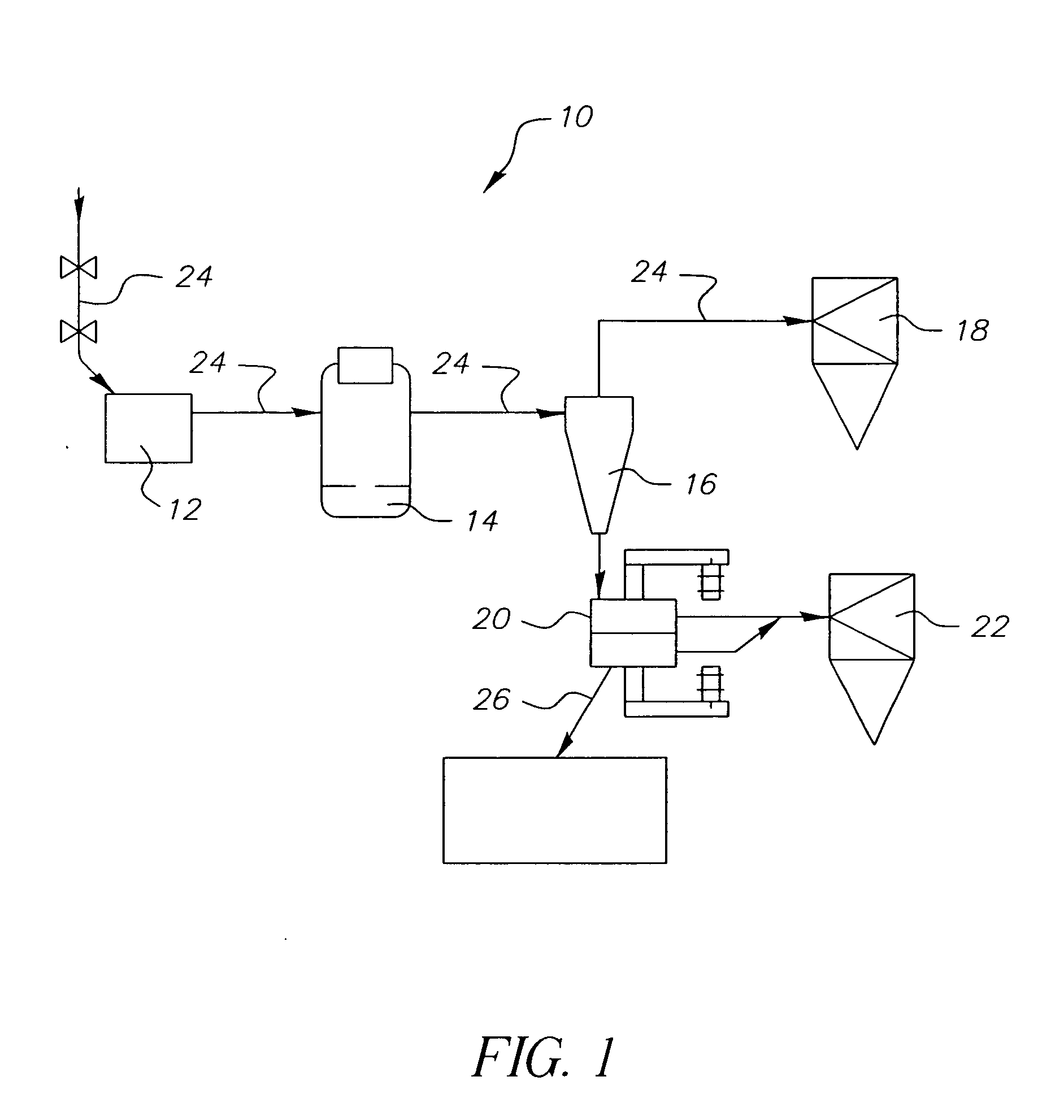
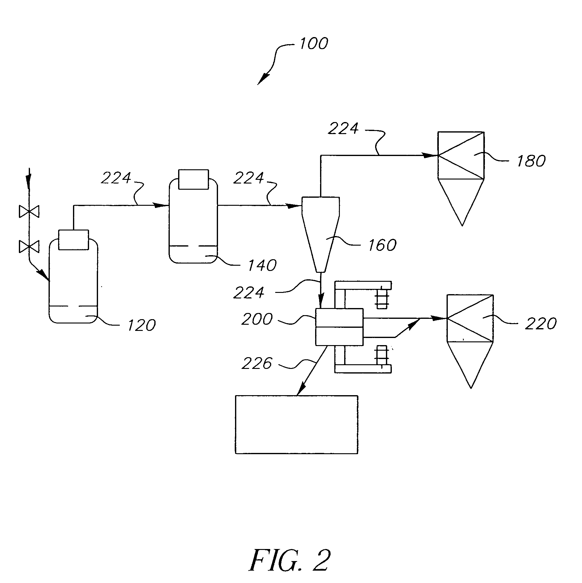
An apparatus (10, 100) for reducing the particle size of a bulk particulate or powder material includes one or more first particle-size reducing stages (12, 120) and a final particle-size reducing stage (14, 140). The first particle-size reducing stage (12, 120) receives the bulk material and reduces the particle size thereof to an intermediate particle size. The final particle-size reducing stage (14, 140) receives the bulk material having the intermediate particle size and further reduces the particle size thereof from the intermediate particle size to a desired particle size.

Description

FIELD OF THE INVENTION [0001] The present invention relates to the production of fine particulate material, such as toner for use in electrophotographic printing machines and other fine particulate material. BACKGROUND OF THE INVENTION [0002] The toner used in electrophotographic printing machines is a blend of materials, including plastic resins, coloring pigments and other ingredients. Most toners are produced in bulk using a melt mixing or hot compounding process. Plastic resins, carbon black, magnetic iron oxides, waxes and charge control agents are blended together while in a molten state to thereby form a hot paste having a consistency similar to cake mix. This mixture is then cooled, typically by forming it into slabs on a cooling belt or by pelletizing the mixture and cooling the pellets. The raw toner is then ground or pulverized into a toner powder by, for example, jet mills or air-swept hammer mills. This process produces a powder having a wide range of particle sizes. Th...

Claims


Application Information

Patent Timeline
IPC IPC(8): B02C21/00B02C23/14
CPCB02C23/14B02C21/00
Inventor STACHOWSKI, MARK J.BLAIR, STEWART W.
Owner EASTMAN KODAK CO
Learn More