Vehicle mounted satellite antenna system with in-motion tracking using beam forming

Inactive Publication Date: 2005-07-07
RENDA TRUST
View PDF19 Cites 23 Cited by
  • Summary
  • Abstract
  • Description
  • Claims
  • Application Information

AI Technical Summary

Benefits of technology

[0017] The present invention relates to a vehicle mountable satellite antenna as defined in the claims which is operable while the vehicle is in motion. The satellite antenna of the present invention can be installed on top of (or embedded into) the roof of a vehicle. The antenna is capable of providing high gain and a narrow antenna be

Problems solved by technology

This results in further beam tilting away fro

Method used


Image

  • Vehicle mounted satellite antenna system with in-motion tracking using beam forming
  • Vehicle mounted satellite antenna system with in-motion tracking using beam forming
  • Vehicle mounted satellite antenna system with in-motion tracking using beam forming

Examples


Embodiment Construction

[0046] Reference will now be made in greater detail to a preferred embodiment of the invention, an example of which is illustrated in the accompanying drawings. Wherever possible, the same reference numerals will be used throughout the drawings and the description to refer to the same or like parts.

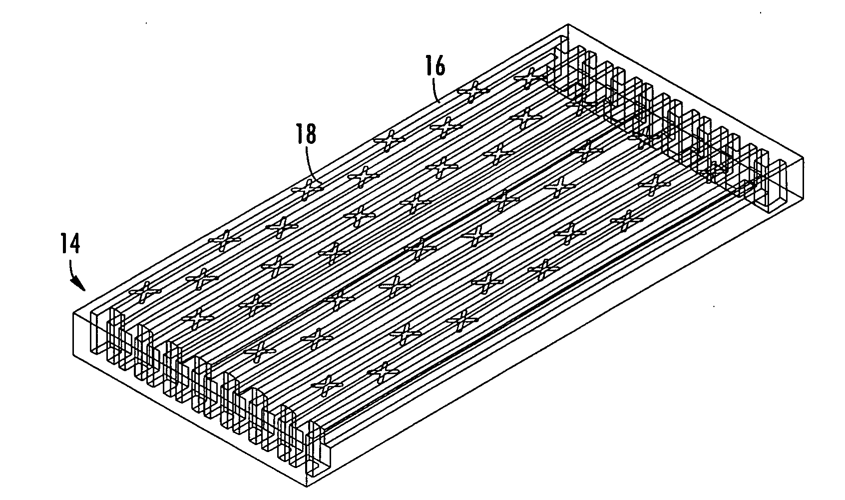
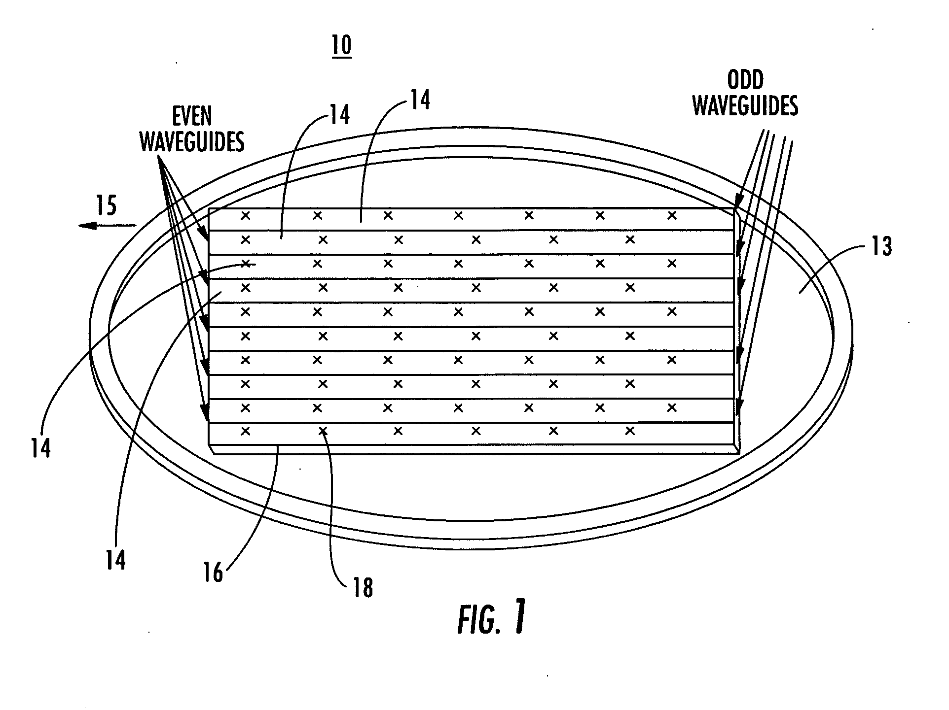
[0047]FIG. 1 is a schematic diagram of antenna system 10 in accordance with the teachings of the present invention. Waveguide antenna 12 comprises an antenna array formed of a plurality of waveguides 14 positioned parallel to each other on horizontal platform 13. Horizontal platform 13 is rotatable under mechanical steering and motion control for aiming the antenna in the azimuth direction.

[0048] Waveguide axis 15 is in a direction perpendicular to the antenna aiming. Radiating surface 16 is the broad side facing the zenith direction. Radiating surface 16 of the waveguide antenna 12 includes a plurality of radiating elements 18 distributed at uniform spacing along waveguide axis 15. Rad...


PUM


Abstract

The present invention relates to a vehicle mountable satellite antenna as defined in the claims which is operable while the vehicle is in motion. The satellite antenna of the present invention can be installed on top of (or embedded into) the roof of a vehicle. The antenna is capable of providing high gain and a narrow antenna beam for aiming at a satellite direction and enabling broadband communication to vehicle. The present invention provides a vehicle mounted satellite antenna which has low axial ratio, high efficiency and has low grating lobes gain. The vehicle mounted satellite antenna of the present invention provides two simultaneous polarization states. In one embodiment, a hybrid mechanic and electronic steering approach provides a more reasonable cost and performance trade-off. The antenna aiming in the elevation direction is achieved via control of an electronic beamforming network. The antenna is mounted on a rotatable platform under mechanical steering and motion control for aiming the antenna in the azimuth direction. Such approach significantly reduces the complexity and increases the reliability of the mechanical design. The antenna height is compatible to the two-dimensional electronic steering phased-array antenna. Additionally, the number of the electronic processing elements required is considerably reduced from that of the conventional two-dimensional electronic steering phased-array antenna, thereby allowing for low cost and large volume commercial production. The present invention provides electronically generated left, right, up, and down beams for focusing the antenna beam toward the satellite while the vehicle is moving. All of the beams are simultaneously available for use in the motion beam tracking. This provides much faster response and less signal degradation.

Description

BACKGROUND OF THE INVENTION [0001] 1. Field of the Invention [0002] The invention relates to vehicle mounted satellite antennae. More particularly, the invention relates to a slotted waveguide planar vehicle mounted satellite antenna with simultaneous dual polarization states, which can employ a hybrid electronic and mechanic steering mechanism, and is operable while the vehicle is in motion. [0003] 2. Related Art [0004] It has long been known how to mount a satellite antenna (dish) atop a vehicle for purposes of communicating with a geostationary or other type of satellite. The initial applications for mounting a satellite dish on a vehicle were military communication and remote television news broadcasting. Consequently, the first methods of mounting a satellite dish included a telescoping mast which was hingedly coupled to the vehicle. When the vehicle was in motion, the mast would be retracted and folded with the satellite dish lying end up on the roof or a side wall of the vehi...

Claims


Application Information

Patent Timeline
IPC IPC(8): G01S3/14G01S3/40G01S3/42H01Q1/32H01Q3/04H01Q13/10H01Q21/00
CPCG01S3/14G01S3/40H01Q21/005H01Q1/3275H01Q3/04G01S3/42
Inventor WANG, JAMES JUNE-MINGYANG, CHAU CHINLIU, FRANKLIN XIAOTIANCHEN, YOURENWANG, WENZHANG
Owner RENDA TRUST
Why Eureka
Try Eureka