Magnetic recording medium, magnetic storage and method for reproducing information from magnetic recording medium

Inactive Publication Date: 2005-07-07
SHOWA DENKO KK
View PDF29 Cites 27 Cited by
  • Summary
  • Abstract
  • Description
  • Claims
  • Application Information

AI Technical Summary

Benefits of technology

[0035]FIGS. 3A and 3B partially show a vertical magnetic recording medium for illustrating a principle of the present invention. As shown, the vertical magnetic recording medium 14 according to the present invention has recording layers including a first magnetic layer 15, a second magnetic layer 16, and a non-magnetic coupling layer 13 formed therebetween. The first and second magnetic layers 15 and 16 are controlled by a film thickness of the non-magnetic coupling layer 13 or such and make antiferromagnetically exchange coupling therebetween, and, in a state in which no external magnetic field is applied, magnetization in the first magnetic layer 15 and magnetization in the second magnetic layer 16 are oriented perpendicular to the film surface in anti-parallel to one another. In this case, a magnetic field leaking from the first and second magnetic layers 15 and 16, i.e., a magnetic field Hy which is used for reproducing information from the magnetic recording medium 14 by means of a magnetic head, is in proportion to the net residual area magnetization |Mr1×t1−Mr2×t2| of the first and second magnetic layers 15 and 16 where Mr1 and Mr2 denote respective ones of residual magnetization in the first magnetic layer 15 and residual magnetization in the second magnetic layer 16, and t1 and t2 denote respective film thicknesses. In a case where the Curie temperature of the first magnetic layer 15 is lower than that of the second magnetic lay

Problems solved by technology

However, when the magnetocrystalline anisotropy is increased, a coercive force increases, a head magnetic field in a head required for carrying out recording increases, and thus, overwrite performance is deteriorated.
However, it is very difficult to develop a material having a further higher Bs.
However, in this method, there are limits in increasing a laser power and in reducing a spot size

Method used


Image

  • Magnetic recording medium, magnetic storage and method for reproducing information from magnetic recording medium
  • Magnetic recording medium, magnetic storage and method for reproducing information from magnetic recording medium
  • Magnetic recording medium, magnetic storage and method for reproducing information from magnetic recording medium

Examples


Example

[0059] A first embodiment of the present invention is described now.

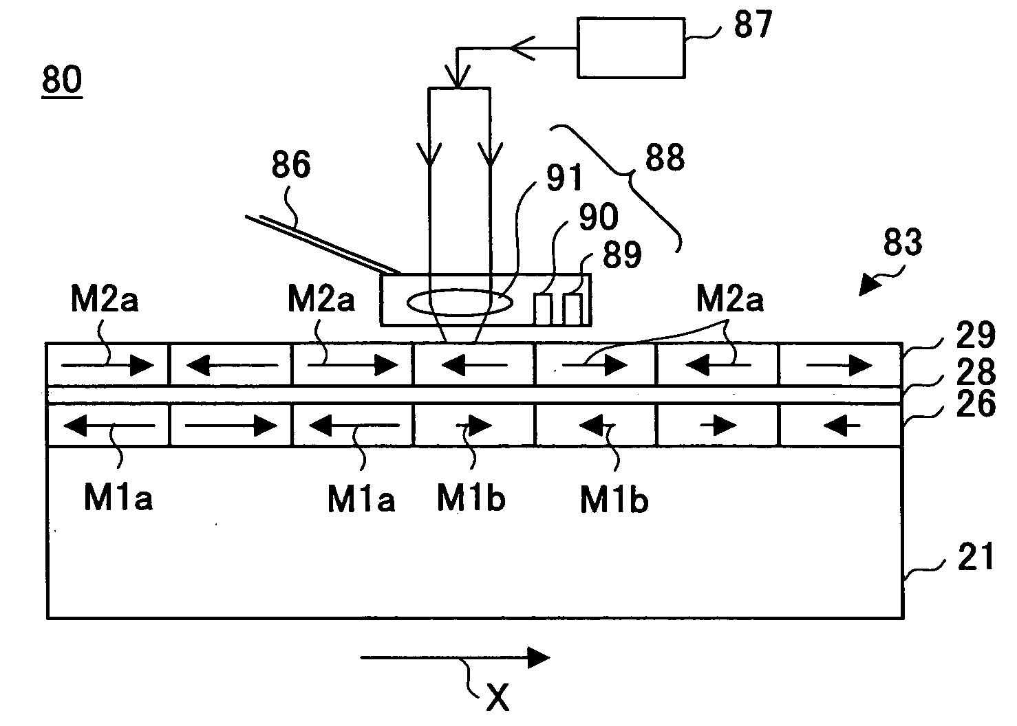
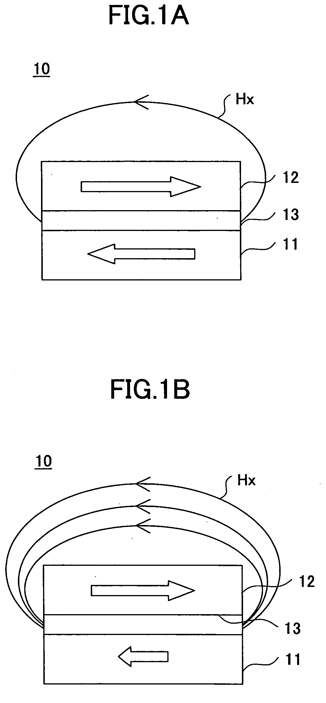
[0060]FIG. 4 shows an elevational sectional view of an in-plane magnetic recording medium according to a first embodiment of the present invention. As shown, the in-plane magnetic recording medium according to the first embodiment includes a substrate 21, and, thereon, a first seed layer 22, a second seed layer 23, a foundation layer 24, a non-magnetic intermediate layer 25, a first magnetic layer 26, a non-magnetic coupling layer 28, a second magnetic layer 29, a protective layer 30 and a lubrication layer 31 are formed in the stated order. The in-plane magnetic recording medium 20 has an exchange coupling structure in which the first magnetic layer 26 and the second magnetic layer 29 make antiferromagnetically exchange coupling therebetween via the non-magnetic coupling layer 28. There, magnetization oriented in an in-plane direction in the first magnetic layer 26 and the second magnetic layer 29 is oriented in a...

Example

[0086] A second embodiment of the present invention is described next. FIG. 7 shows an elevational sectional view of a vertical magnetic recording medium according to the second embodiment of the present invention. In the figure, the same reference numerals are given to parts corresponding to those described above, and duplicated description is omitted.

[0087] As shown, the vertical magnetic recording medium 40 according to the second embodiment of the present invention has a configuration in which, on a substrate 21, a soft magnetic backed layer 41, a seed layer 42, a non-magnetic intermediate layer 43, a first vertical magnetic film 44, a non-magnetic coupling layer 28, a second vertical magnetic film 45, a protective layer 30 and a lubrication layer 31, laminated in the stated order.

[0088] The soft magnetic backed layer 41 has a thickness of, for example, in a range between 50 nm and 2 μm, and is made from an amorphous or micro crystalline alloy containing at least one element s...

Example

[0099] A third embodiment of the present invention is described next. FIG. 8 shows an elevational sectional view of a patterned medium according to the third embodiment of the present invention. The same reference numerals are given to parts corresponding to those described above, and duplicated description is omitted.

[0100] As shown in FIG. 8, the patterned medium 50 includes a substrate 21, laminated members 51 cyclically arranged on the substrate 21, and non-magnetic parts 52 separating these laminated members 51 from each other. Each of the laminate members 51 has the same configuration as that of the in-plane magnetic recording medium according to the first embodiment or the vertical magnetic recording medium according to the second embodiment described above. Here, the in-plane magnetic recording medium is used as an example. For the purpose of simplification of description, only the first magnetic layer 28, the non-magnetic coupling layer 28 and the second magnetic layer 29 ...


PUM


Abstract

A magnetic recording medium includes a first magnetic layer; and a second magnetic layer formed on the first magnetic layer. The first magnetic layer and the second magnetic layer make exchange coupling therebetween and also, have their magnetizing direction in anti-parallel to one another. A net residual area magnetization of the first magnetic layer and the second magnetic layer is expressed by the following formula: |Mr1×t1−Mr2×t2| where Mr1 and Mr2 denote respective residual magnetizations of the first magnetic layer and the second magnetic layer, and t1 and t2 denote respective film thicknesses of them; and the net area magnetization at a first temperature is larger than the net area magnetization at a second temperature lower than the first temperature.

Description

BACKGROUND OF THE INVENTION [0001] 1. Field of the Invention [0002] The present invention relates to magnetic recording medium, a magnetic storage and a method for reproducing information from the magnetic recording medium, suitable for high density recording, and, in particular, to a magnetic recording medium, a magnetic storage and a method for reproducing information from the magnetic recording medium in which the magnetic recording medium is selectively heated, and recording / reproduction is performed. [0003] 2. Description of the Related Art [0004] Recently, high density recording has been rapidly promoted at a rate of 100% per year. In an in-plane recording method which is a main trend, it is presumed that the limit of plane recording density is 100 Gb / in2. The reason therefor is that, in a high density recording range, for the purpose of medium noise reduction, a size of a crystal grain which acts as a magnetization unit in a recording layer is reduced, and a zigzag in a magne...

Claims


Application Information

Patent Timeline
IPC IPC(8): G11B5/02G11B5/66G11B5/851G11B11/10G11B11/105
CPCG11B11/10589G11B5/66G11B5/851
Inventor INOMATA, AKIHIROAJAN, ANTONYTAGUCHI, JUNMATSUMOTO, KOJIYAMAGISHI, WATARU
Owner SHOWA DENKO KK
Why Eureka
Try Eureka