Battery can with rupturable safety vent and method of forming

Inactive Publication Date: 2005-07-07
TRUELOVE & MACLEAN
View PDF0 Cites 8 Cited by
  • Summary
  • Abstract
  • Description
  • Claims
  • Application Information

AI Technical Summary

Benefits of technology

[0007] One advantage of a battery can as described above is the uniformity of the exterior surface of the can. Uniformity of the exterior surface (i.e., the lack of sharp interruptions in the surface) improves the external appearance and uniformity of the battery can, also reducing the chances that a nickel-break will form and allow corrosion to gain a foothold on the outer surface of a nickel-plated steel casing.
[0008] One advantage of the use of the roll-forming process to incorporate the vents into the battery cans is substantial uniformity of the physical attributes of the vents across production quantities. Because the physical attributes across production quantities of cans are substantially uniform, each individual battery of a particular type c

Problems solved by technology

The incorporated failure joint provides a weakness that ruptures and compromises the structural integrity of the can when the can is subjected to excessive internal pressure.
Stamping a groove into the can, however, because of the impact forces required and the disparate fragility of the can, oftentimes results in a vent that is not uniform in depth over its length, which may provide a vent that will rupture at a pressure that is different from the pressure at which the vent is calculated to rupture.
Furthermore, because the stamping operation typically requires a high impact force, significant wear of the stamping tool may be realized over relatively short production

Method used


Image

  • Battery can with rupturable safety vent and method of forming
  • Battery can with rupturable safety vent and method of forming
  • Battery can with rupturable safety vent and method of forming

Examples


Embodiment Construction

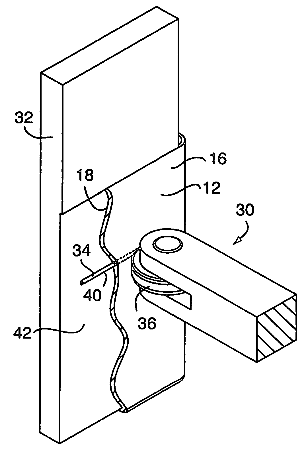
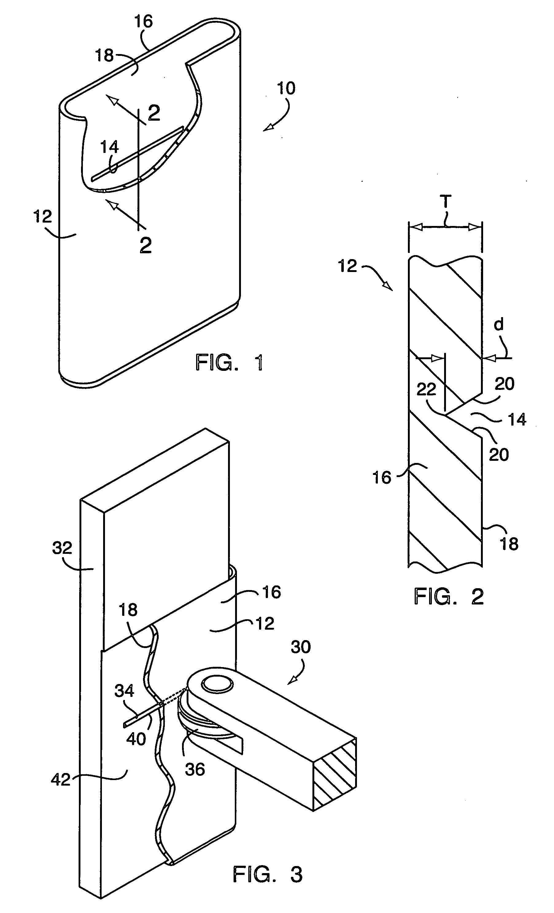
[0016] Referring to FIG. 1, a battery can for a prismatic lithium primary battery cell is shown generally at 10. The battery can 10 comprises a casing 12 having a rupturable safety vent 14 formed or otherwise disposed on an interior surface of the casing 12. The term “vent” as used throughout the description does not mean an existing opening in the casing wall, but rather a weakened section of the casing wall that will rupture at a predetermined location under predetermined conditions. The vent 14 will rupture in response to a condition internal to the battery cell (e.g., a buildup of pressure within the cell). A top end and a bottom end of the can 10 are configured to receive suitable closure elements (e.g., an electrode cap and an electrode base) upon filling of the can 10 with an electrolyte. Although the casing 12 is illustrated hereinafter as being prismatic in shape, it should be understood that the casing is not limited to being prismatic in shape. Other shapes in which the c...


PUM

PropertyMeasurementUnit
Pressureaaaaaaaaaa

Abstract

A battery can comprises a casing and a vent formed on a interior surface of the casing, the vent being rupturable by a condition internal to a battery cell in which the battery can is employed. The vent is a roll-formed groove disposed on the interior surface such that a weakness is defined in the casing. Upon encountering a buildup of excessive pressure in the battery cell, the vent ruptures, thereby compromising the structural integrity of the casing and relieving the pressure. A method of forming a rupturable vent in a casing of a battery cell comprises positioning the casing adjacent to a tool such that a first surface of the casing faces the tool and biasing the casing against the tool to form a groove in the first surface. A method of forming a battery can comprises forming a casing and roll-forming a rupturable vent in an interior surface of the casing.

Description

TECHNICAL FIELD [0001] This invention relates in general to battery cans with rupturable safety vents and methods of forming battery cans with such vents. More particularly, this invention relates to a battery can having such a vent that is formed on an interior surface of the can. BACKGROUND OF THE INVENTION [0002] Disposable and rechargeable battery cells are utilized in a wide variety of applications to provide either a main source of power or backup power to a wide variety of devices. These cells may contain acidic or alkaline electrolytic pastes in metal cans. The cans are fabricated from thin metal sheeting, such as nickel-plated steel, aluminum and stainless steel, and have zinc and carbon, or zinc and manganese oxide or other type of electrodes. The cans are typically manufactured in standard sizes such as A, AA, AAA, C, D, etc. for applications such as toys, flashlights, portable radios, and the like. They may also be manufactured in specialty sizes or in prismatic shapes f...

Claims


Application Information

Patent Timeline
IPC IPC(8): B26D1/18B26D1/20B26D3/08B26D7/20H01M50/119H01M50/124
CPCB26D1/185B26D1/205B26D3/085H01M2/1241B26D2007/202H01M2/0275H01M2/0285B26D7/20Y10T83/0385Y02E60/10H01M50/3425H01M50/124H01M50/119
Inventor MALEC, FRANCIS M.
Owner TRUELOVE & MACLEAN
Why Eureka
Try Eureka