Methods of correcting a luminescence value, and methods of determining a corrected analyte concentration

a luminescence value and luminescence correction technology, applied in the field of luminescence value correction methods, can solve the problems of slow progress with these approaches, high or low glucose or other analytes may have detrimental effects, and patients may not be comfortable using this method

Inactive Publication Date: 2005-07-07
BECTON DICKINSON & CO
View PDF9 Cites 182 Cited by
  • Summary
  • Abstract
  • Description
  • Claims
  • Application Information

AI Technical Summary

Problems solved by technology

For example, high or low levels of glucose or other analytes may have detrimental effects.
Patient compliance using this method is problematic due to pain caused by frequent (several times per day) sticks.
Progress with these approaches has been slow due to the requirement for frequent calibration, reproducible sample illumination, and variances in spectroscopic backgrounds between individuals.
These sensors are subject to inaccurate measurement due to oxygen deficiency and buildup of oxidation by-products.
Also, the electrochemical reaction itself generates a buildup of oxidation byproducts that may inhibit and degrade both the enzyme and its protective layer.
Although this is an optical biosensor, with the fluorescence signal level varying with changing oxygen levels, such a sensor is subject to the same problems as amperometric devices based on this same chemistry: oxygen deficiency and enzyme degradation.
Labeled concanavalin A and dextran have been used to create a competitive FRET assay; however,

Method used


Image

  • Methods of correcting a luminescence value, and methods of determining a corrected analyte concentration
  • Methods of correcting a luminescence value, and methods of determining a corrected analyte concentration
  • Methods of correcting a luminescence value, and methods of determining a corrected analyte concentration

Examples


example 1

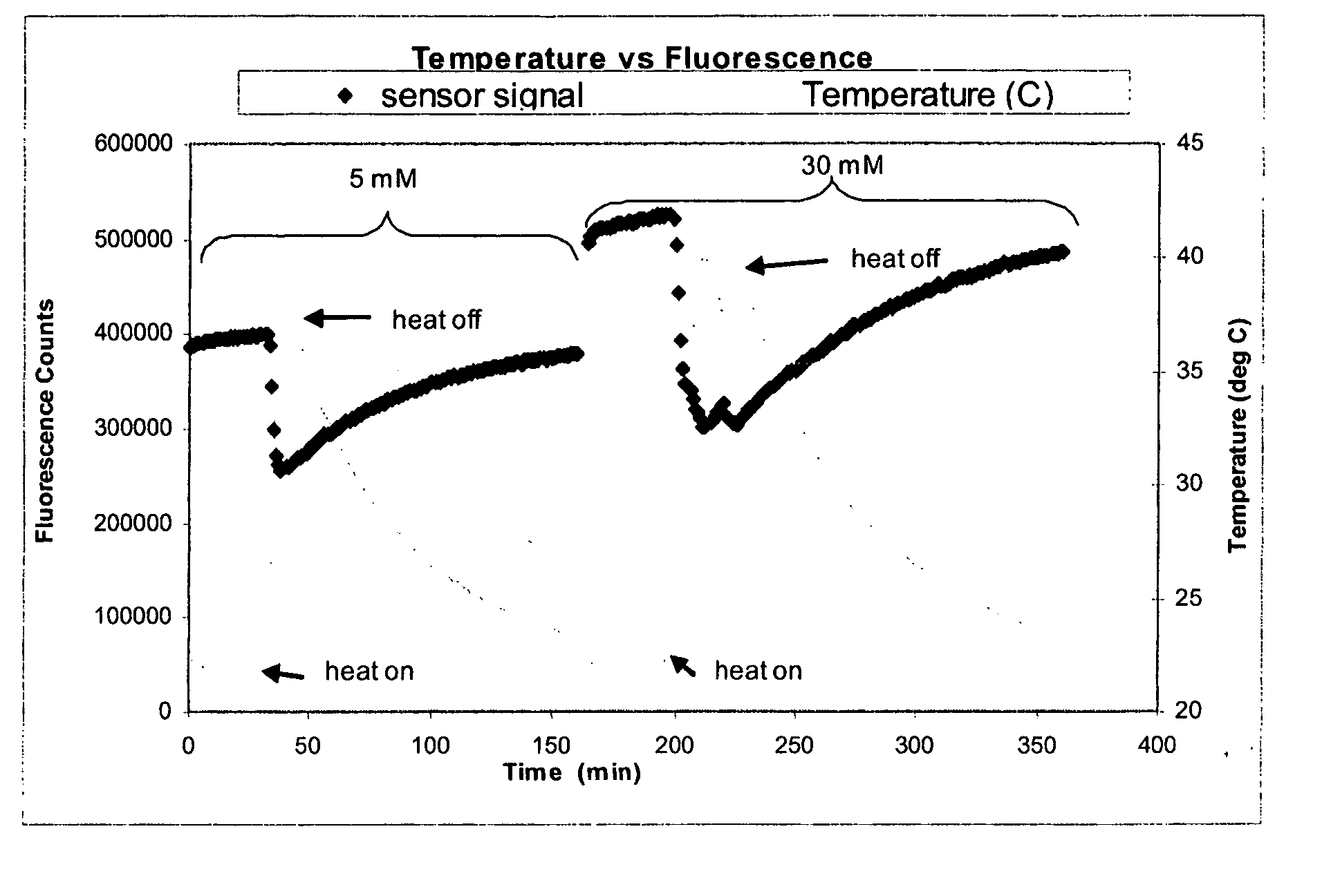
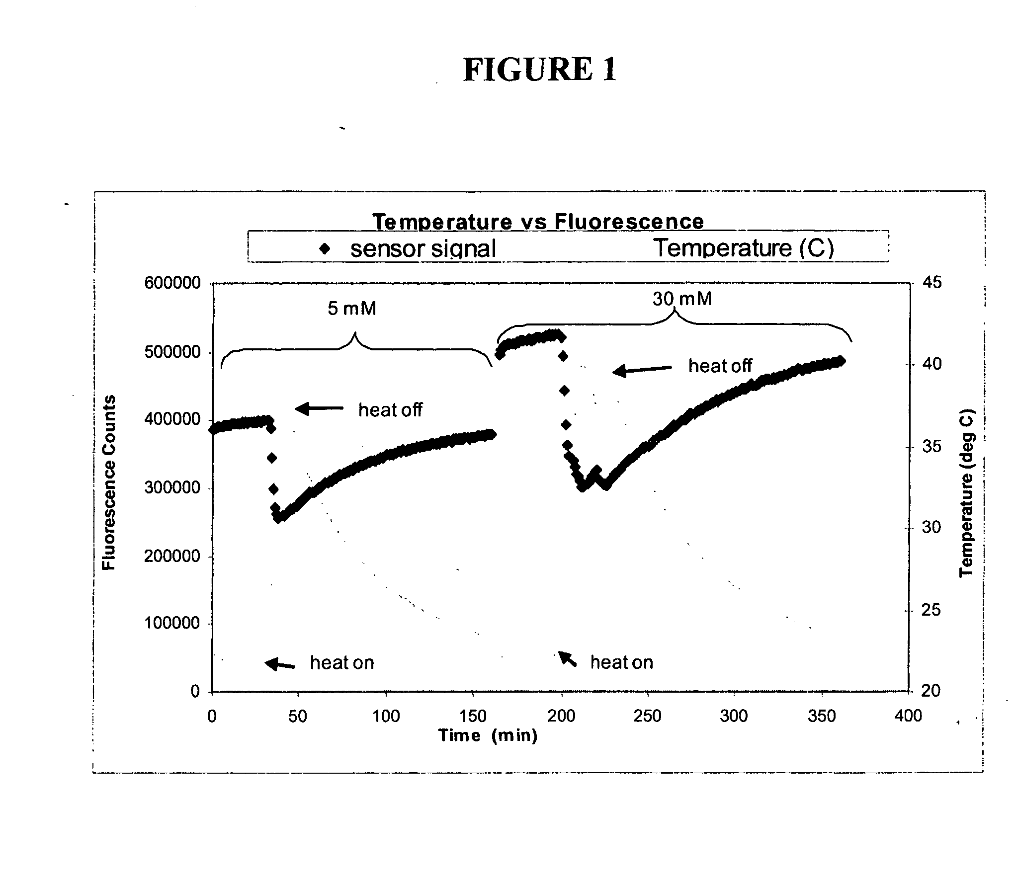
[0161] The objective of this experiment was to determine whether Continuous Glucose Monitoring System (“CGMS”) sensors are sensitive to temperature, and if so, to determine the magnitude and repeatability of the sensitivity. This experiment depicts, inter alia, calculations for correcting fluorescence if temperature is measured independently.

Experimental Methods

[0162] Several experiments were performed using various optical sensors (fiber-in-needle). Sensors were placed in scintillation vials containing glucose solutions (5 and 30 mM) and which were located in a heating block. The block temperature was cycled from room temperature to 40° C. and back to room temperature once for each glucose concentration. Sensor fluorescence and solution temperature data were collected. Sample data from one of those experiments are depicted in FIG. 1. Oscillations about the set point are due to the heating block controller.

Data Analysis

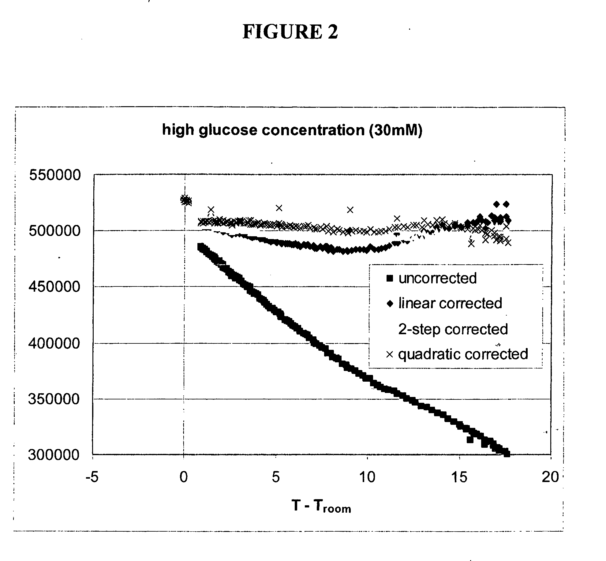
[0163] For each experiment, temperature differences were c...

example 2

[0187] An example of temperature correction using a second luminescent reporter is presented below. In this example, both the sensing and reference reporting groups have temperature sensitivities largely quadratic in temperature, but the magnitude of sensitivity differs for each. In this example the reference reporting group is the same dye as used in the sensor, but is attached to a binding protein which is not sensitive to the presence of analyte over the range of expected analyte concentrations. In other embodiments, the reference dye could have different excitation / emission properties than the sensing group.

Experimental Methods

[0188] Experiments were performed using various optical sensors (fiber-in-needle) with one of two protein-dye combinations. Sensors were placed in scintillation vials containing 30 mM glucose solutions and which were located in a heating block. The block temperature was cycled from room temperature to 35° C. and back to room temperature twice. Sensor fl...


PUM

PropertyMeasurementUnit
Temperatureaaaaaaaaaa
Concentrationaaaaaaaaaa
Fluorescenceaaaaaaaaaa

Abstract

The invention is directed to methods of correcting a luminescence value, and methods of determining a corrected analyte concentration, by use of a device capable of providing a signal when a binding protein binds to at least one analyte, and a thermometer. The invention is also directed to systems which include such a device, and a processor for correcting measured luminescence of a reporter group based on a measured temperature. The invention is further directed to apparatuses that include a memory for storing luminescence information and temperature information, and a processor for correcting luminescence information. The invention is further directed to computer programs for executing the methods of the invention, and machine-readable storage medium on which programs are recorded.

Description

CROSS REFERENCE TO RELATED APPLICATIONS [0001] The present invention is a continuation-in-part of co-pending U.S. patent application Ser. No. 10 / 967,220, filed on Oct. 19, 2004, which is a continuation-in-part of U.S. patent application Ser. No. 10 / 721,797, both of which applications are incorporated herein by reference in their entirety.FIELD OF THE INVENTION [0002] The present invention is directed to methods of correcting a luminescence value, and / or methods of determining a corrected analyte concentration, by use of a device having at least one binding protein having at least one reporter group attached thereto, and a thermometer. The present invention is also directed to systems that include such devices and a processor for correcting measured luminescence of a reporter group based on a measured temperature. The present invention is further directed to computer programs for executing the methods of the invention, and computer or machine-readable storage medium on which programs...

Claims


Application Information

Patent Timeline
IPC IPC(8): G01N21/77G01N33/542G01N33/543
CPCA61B5/14532A61B5/1455A61B5/1459A61B5/1495A61B2560/0223A61B2560/0252G01N2201/1211G01N21/6428G01N21/7703G01N33/542G01N33/54373G01N2021/7786G01N21/274
Inventor KEITH, STEVENPALMER, PHYLLIS J.
Owner BECTON DICKINSON & CO
Why Eureka
Try Eureka