Treatment of tattoos by photodynamic therapy

Inactive Publication Date: 2005-07-07
QLT INC
View PDF29 Cites 9 Cited by
  • Summary
  • Abstract
  • Description
  • Claims
  • Application Information

AI Technical Summary

Benefits of technology

[0012] While not wishing to be bound by theory, it is believed that the photodynamic therapy causes the fragmentation of tattoo ink particles, possibly by disrupting the ink-loaded dermal cells, which results in the release of the ink pa

Problems solved by technology

While not wishing to be bound by theory, it is believed that the photodynamic therapy causes the fragmentation of tatto

Method used


Image

  • Treatment of tattoos by photodynamic therapy
  • Treatment of tattoos by photodynamic therapy
  • Treatment of tattoos by photodynamic therapy

Examples


example 1

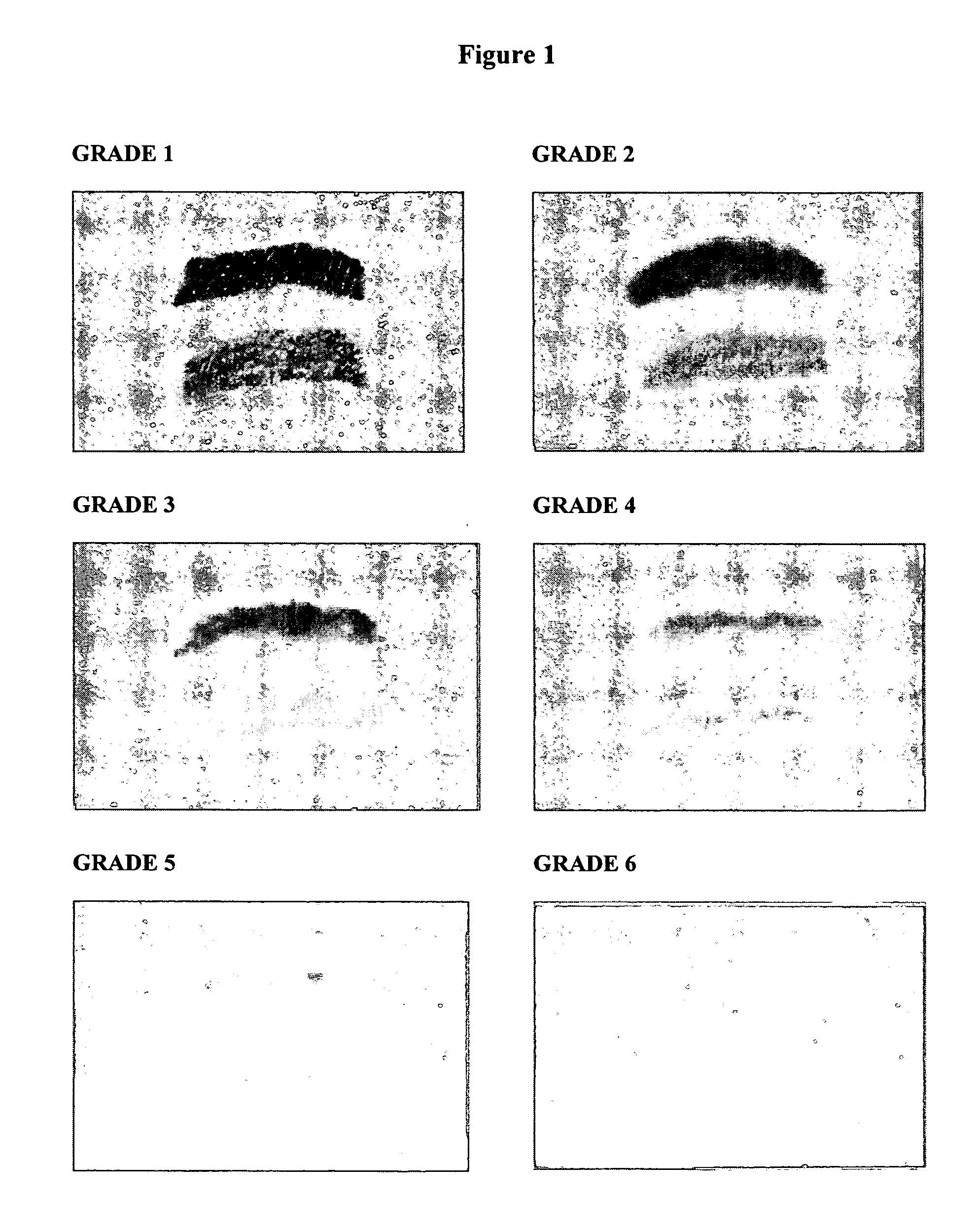
[0074] Five guinea pigs were lightly anesthetized and shaved. Depilation of remaining hair was carried out using Nair®. Tattoos were applied using the Aims IIIA Tattoo Identification System with a 3-prong needle (Aims Inc, Hornell N.Y.) set at a penetration depth of 1 mm. Tattoo lines were applied side by side to create a rectangular filled area approximately 3×10 mm. Black ink (pigment #242, Aims Inc, Hornell N.Y.) and green / blue ink (pigment #270, Aims Inc, Hornell N.Y.) were used.

[0075] Three pairs of rectangles approximately 3×10 mm each were tattooed on each flank of each animal for a total of 6 tattoo sites on each flank. One tattoo of each pair was created using black ink, the other using green / blue ink. The tattoo pairs were side by side, at least 1 cm apart, on the animal's flank as shown in FIG. 1. The pattern was repeated on the opposite flank.

[0076] QLT0074 for injection (A-EA6 in U.S. Pat. No. 5,929,105) was reconstituted with Water for Injection to give a stock conce...

example 2

[0085] A tattooed human male having skin type II is given a skin photosensitivity test on skin area near the tattoo. No adverse skin reaction is observed. The skin over the tattooed area is shaved and the surface area estimated to be 3cm2.

[0086] QLT0074 for Injection is reconstituted with Water for Injection to give a stock concentration of 2.0 mg / ml and diluted with 5% Dextrose in water to a concentration of 0.2 mg / ml. The skin surface is cleaned and alcohol-disinfected. 30 intradermal injections are given using a syringe and a 30 gauge ½ long needle. The injections are at a depth of approximately 3 mm and spaced evenly across the tattoo. The total volume of composition injected is 0.5 mL. The skin is then wiped with gauze to remove any excess drug.

[0087] A template mimicking the tattooed area is applied on skin to limit the light exposure to the target area. Fifteen minutes after injection of the drug, the skin is exposed to 10 J / cm2 of LED-generated red light (688 nm-Q-100 LED ...

example 3

[0088] A tattooed human female having skin type II is given a skin photosensitivity test on skin area near the tattoo. No adverse skin reaction is observed. The skin over the tattooed area is shaved and the surface area estimated to be 4.5 cm2.

[0089] A Macroflux® transdermal patch is treated with topical photosensitizer ointment (comprising 0.2 wt % lemuteporfin, 50 wt % PEG-200, 24 wt % Transcutol®, 10 wt % PEG-3350 and 15.8 wt % oleyl alcohol) and then applied to the tattooed area. The Macroflux patch incorporates a thin titanium screen with microprojections that, when applied to the skin, creates superficial pathways through the skin's barrier layer allowing penetration of the photosensitizer. The patch is left in place for 1-2 hrs and then removed. Any excess photosensitizer is wiped away.

[0090] A template mimicking the tattooed area is applied on skin to limit the light exposure to the target area. The skin is then exposed to 15 J / cm2 of LED-generated red light (688 nm-Q-100 ...


PUM

PropertyMeasurementUnit
Fractionaaaaaaaaaa
Fractionaaaaaaaaaa
Fractionaaaaaaaaaa

Abstract

The present invention relates to a photodynamic method of treating tattoos. The method comprises: (i) intradermally and/or locally delivering photosensitizer into tattooed target tissue; and (ii) irradiating the target tissue with activation energy at a wavelength appropriate to activate the photosensitizer. The present method causes the tattoo inks to fade or disappear completely. In preferred embodiments the tattoo will fade by at least 25%, more preferably at least 50%, even more preferably at least 75%.

Description

RELATED PATENT APPLICATIONS [0001] This application claims priority to Canadian Patent Application no. 2437638 filed 20 Aug. 2003 which is incorporated in its entirety herein by reference. FIELD OF THE INVENTION [0002] The present invention relates to photodynamic therapy (PDT). In particular, the present invention relates to photodynamic methods, compositions, and devices for the treatment of tattoos. BACKGROUND OF THE INVENTION [0003] Tattooing is an invasive procedure where pigments, typically permanent ones, are introduced into the skin. Dating back to at least the ancient Egyptians, tattooing has been documented in a variety of cultures and for a variety of motivations. For example, the tattoos of New Zealand's pre-colonial Maori population were both decorative and an expression of an individuals legal identity. Indeed, in the early days of the colonial era, Maoris would often sign European documents by painstakingly drawing their entire facial design. In modern-day western cul...

Claims


Application Information

Patent Timeline
IPC IPC(8): A61B17/00A61B18/20A61N5/06
CPCA61B18/203A61B2017/00769A61B2018/00452A61Q19/02A61K2800/434A61N5/062A61Q1/145A61K8/02A61P17/02
Inventor KJELLBOTN, CHARLES R.MARGARON, PHILIPPE MARIA C.MCNICOL, PATRICIA J.NORTH, JOHN R.
Owner QLT INC
Why Eureka
Try Eureka