Audio decoding apparatus and method

a bandwidth expansion and decoding technology, applied in the field of audio decoding apparatus and decoding method for audio bandwidth expansion system, can solve the problems of complex-valued synthesis filter bank that cannot be replaced by real-valued synthesis filter bank, power consumption increases, and audio degradation, etc., to suppress aliasing and suppress audio degradation

Active Publication Date: 2005-07-07
PANASONIC CORP +1
View PDF8 Cites 155 Cited by
  • Summary
  • Abstract
  • Description
  • Claims
  • Application Information

AI Technical Summary

Benefits of technology

[0022] Thus comprised, our invention suppresses aliasing in the real-value subband signal due to different gain being applied to each high frequency ...

Problems solved by technology

Accordingly when the decoder is implemented using integrated circuits, there is a problem that power consumption increases and the playback time that is possible with a given power supply capacity decreases.
However, because the characteristics of a synthesis filter bank (a real-valued coefficient synthesis fil...

Method used


Image

  • Audio decoding apparatus and method
  • Audio decoding apparatus and method
  • Audio decoding apparatus and method

Examples


embodiment 1

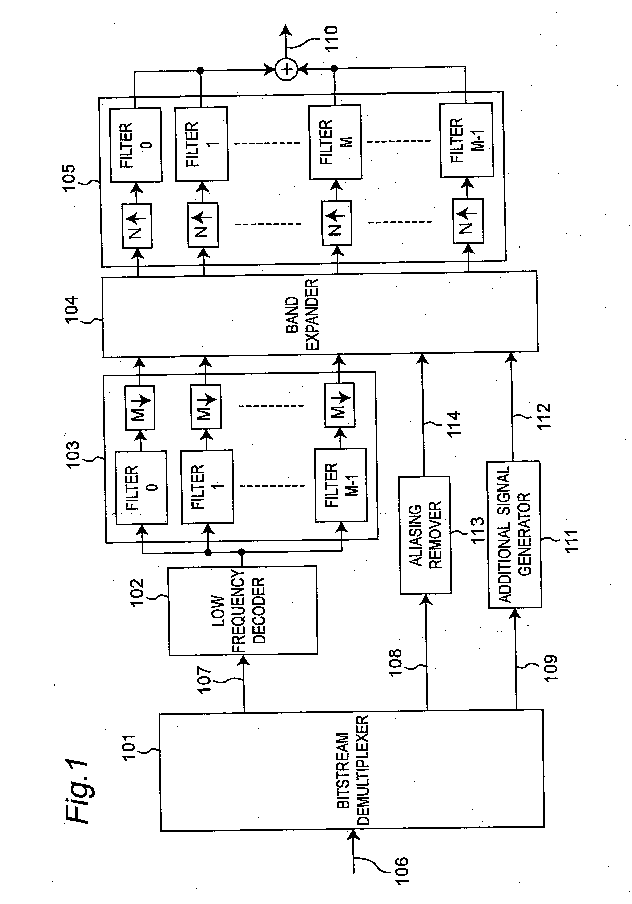
[0032]FIG. 1 is a schematic block diagram showing a decoding apparatus according to a first embodiment of the present invention.

[0033] This decoding apparatus has a bitstream demultiplexer 101, low frequency decoder 102, analysis filter bank 103, band expander (band expanding means) 104, synthesis filter bank 105, aliasing remover 113, and additional signal generator 111.

[0034] The bitstream demultiplexer 101 receives an input bitstream 106 and demultiplexes the bitstream 106 into low frequency component information 107, high frequency component information 108, and additional signal information 109. The low frequency component information 107 has been encoded using the MPEG-4 AAC coding method, for example. The low frequency decoder 102 decodes low frequency component information 107 and generates a time signal representing the low frequency component.

[0035] The resulting time signal representing the low frequency component is then divided into multiple (M) subbands by the analy...

embodiment 2

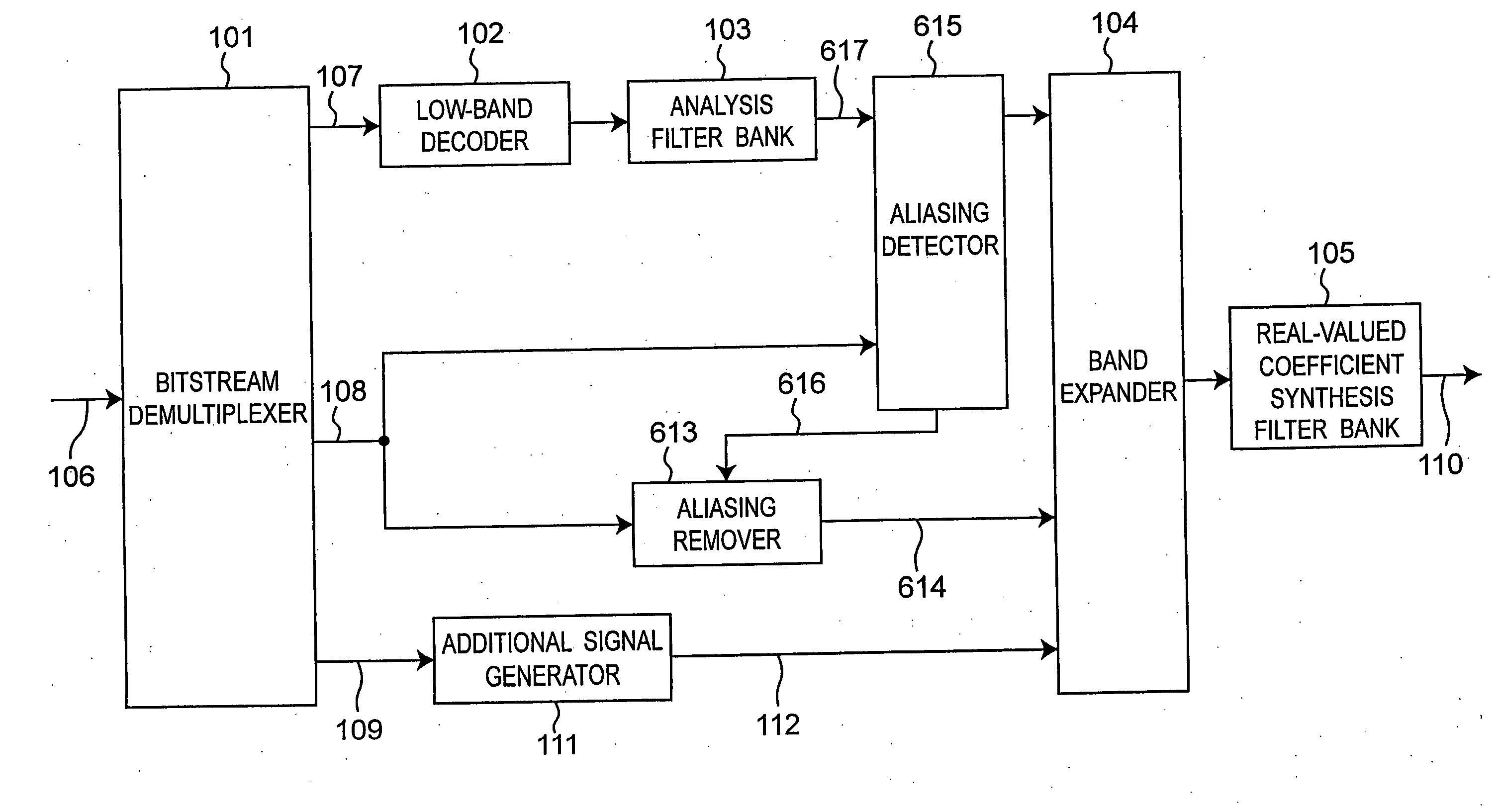
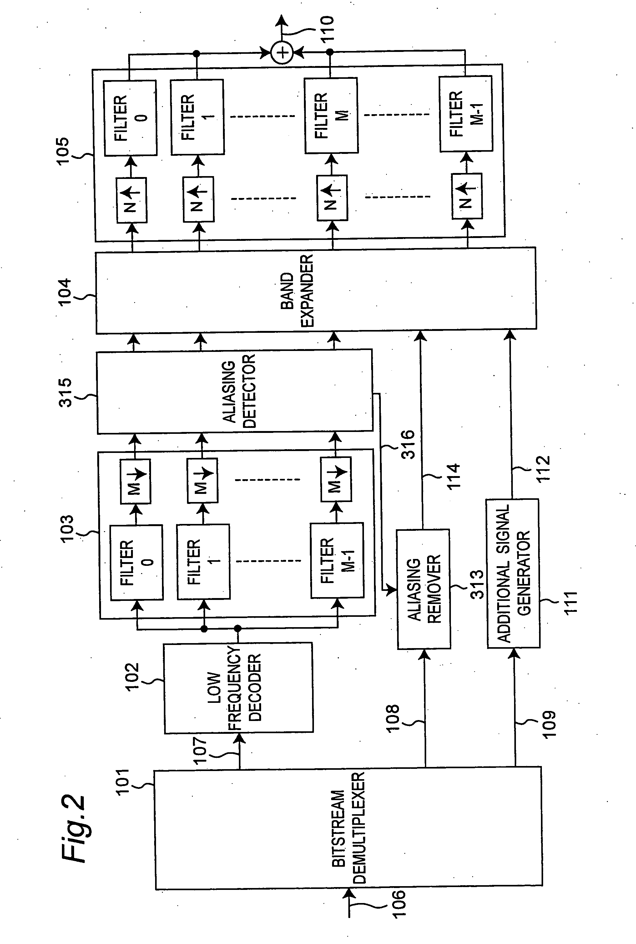
[0052]FIG. 2 is a schematic drawing of a decoding apparatus according to a second embodiment of the present invention. This embodiment differs from the configuration shown in FIG. 1 in the addition of an aliasing detection means (aliasing detector) 315 for detecting subbands where there is a high likelihood of aliasing components being introduced. The detection data 316 output from the aliasing detector 315 is input to aliasing remover 313 which then adjusts the gain of the high frequency components based on the detection data 316.

[0053] Operation of the decoding apparatus according to this second embodiment is the same as that of the first embodiment except for that relating to the aliasing detector 315 and aliasing remover 313. Only the operation of the aliasing detector 315 and aliasing remover 313 is therefore described below.

[0054] The operating principle of the aliasing detector 315 is described first.

[0055] Aliasing cannot logically be avoided insofar as real-valued subban...

embodiment 3

[0079] The aliasing detector 315 in the above second embodiment compares a predetermined threshold value with the reflection coefficients of each subband, and based on the relation between these values detects and outputs as a binary value whether aliasing occurs or not. When the evaluation value changes near the threshold value using a binary value detection method, the aliasing detection value for occurrence / non-occurrence changes frequently. This complicates tracking whether to adjust or not adjust gain, and can adversely affect sound quality.

[0080] The aliasing detector 315 in the present embodiment therefore detects the degree of occurrence of aliasing. That is, rather than using a binary value to simply indicate whether aliasing is detected or not, the occurrence of aliasing is indicated by a continuous value denoting the degree of occurrence of aliasing. Gain is then adjusted based on this continuous value to achieve a smooth transition. Sudden changes in gain caused by cha...


PUM


Abstract

An audio decoding apparatus decodes high frequency component signals using a band expander that generates multiple high frequency subband signals from low frequency subband signals divided into multiple subbands and transmitted high frequency encoded information. The apparatus is provided with an aliasing detector and an aliasing remover. The aliasing detector detects the degree of occurrence of aliasing components in the multiple high frequency subband signals generated by the band expander. The aliasing remover suppresses aliasing components in the high frequency subband signals by adjusting the gain used to generate the high frequency subband signals. Thus occurrence of aliasing can be suppressed and the resulting degradation in sound quality can be reduced, even when real-valued subband signals are used in order to reduce the number of operations.

Description

TECHNICAL FIELD [0001] The present invention relates to a decoding apparatus and decoding method for an audio bandwidth expansion system for generating a wideband audio signal from a narrowband audio signal by using a small amount of additional information, and relates to technology enabling decoding a high audio quality signal with few calculations. BACKGROUND ART [0002] Bandwidth division encoding is a common method of encoding an audio signal at a low bit rate while still achieving a high quality playback signal. This is done by splitting an input audio signal into signals for plural frequency bands (subbands) using a band division filter, or by converting the input signal to a frequency domain signal using a Fourier transform or other time-frequency conversion algorithm, then dividing the signal into multiple subbands in the frequency domain, and allocating an appropriate coding bit to each of the bandwidth divisions. The reason why a high quality playback signal can be obtained...

Claims


Application Information

Patent Timeline
IPC IPC(8): G10L19/00G10L19/02G10L19/03G10L19/093H03M7/30
CPCG10L21/038G10L19/0204
Inventor TANAKA, NAOYASHIMADA, OSAMUTSUSHIMA, MINEONORIMATSU, TAKESHICHONG, KOK SENGKUAH, KIM HANNNEO, SUA HONGNOMURA, TOSHIYUKITAKAMIZAWA, YUICHIROSERIZAWA, MASAHIRO
Owner PANASONIC CORP
Why Eureka
Try Eureka