
Fluid control valve and droplet ejection device

a technology of droplet ejection and control valve, which is applied in the direction of valve housing, digital marking by punching, combustion types, etc., can solve the problems of defective ejection, uneven ejection of cleaning liquid for cleaning the droplet ejection head, and other hydraulic equipment placed in the downstream side of the piping may get a malfunction

Inactive Publication Date: 2005-07-14
SEIKO EPSON CORP
View PDF12 Cites 7 Cited by
  • Summary
  • Abstract
  • Description
  • Claims
  • Application Information

AI Technical Summary

Benefits of technology

The fluid control valve described in this patent has several technical effects. First, it includes an annular element that prevents bubbles from getting built up at the connection points between the couplers and the tank, which prevents them from getting integrated and becoming a large bubble. Second, the annular element is made of synthetic resin, which increases the number of fluid types for which the valve can be used and demonstrates higher elasticity. Third, the invention includes a coupler that is positioned to expand or reduce its diameter without forming any shoulder part, which further prevents bubbles from getting built up. Fourth, the invention includes an inlet port and an outlet port that are positioned at different levels, which prevents bubbles from getting built up in the tank. Fifth, the invention includes a tank with a tilted top surface, which allows any bubble to flow out of the tank. Lastly, the invention includes a surface treatment that makes the tank internal surface liquid-affinitive, which prevents bubbles from adhering to the internal surface.

Problems solved by technology

Thus, there is a chance that other hydraulic equipment placed in a downstream side of the piping may get a malfunction because of the bubble.
Then, the bubble impairs stable ejecting operation of the droplet ejection head, and it may eventually cause defective ejection if the impair is remarkable.
Furthermore, if the bubble gets built up in a fluid control valve of the cleaning liquid supply system to become a greater bubble that blocks up the flow passage, the ejection amount of cleaning liquid for cleaning the droplet ejection head becomes uneven so that a nozzle part of the droplet ejection head is not cleaned enough and eventually a stain may remain at the nozzle part.
If once a stain remains at the nozzle part in such a manner, ink does not get ejected so as to cause a missing operation of drawing and / or a flying route of ink becomes bent so that quality of initial ejection by the droplet ejection head cannot be secured sufficiently.

Method used


Image

  • Fluid control valve and droplet ejection device
  • Fluid control valve and droplet ejection device
  • Fluid control valve and droplet ejection device

Examples


Embodiment Construction

[0035] The following sections explain preferred embodiments of the invention by referring to an exemplary embodiment of the invention.

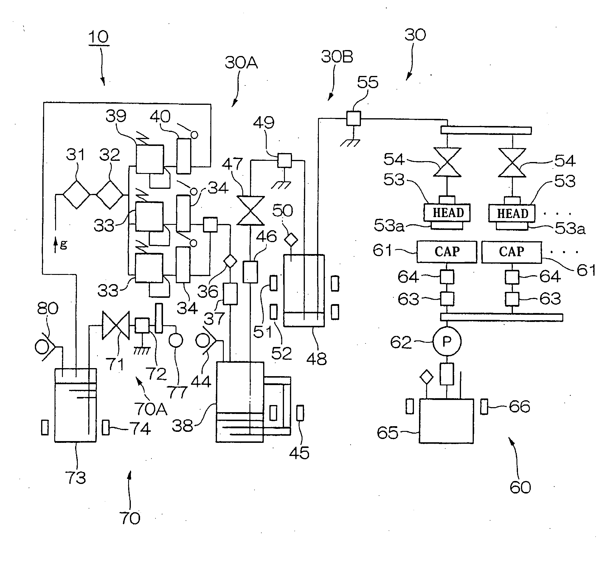
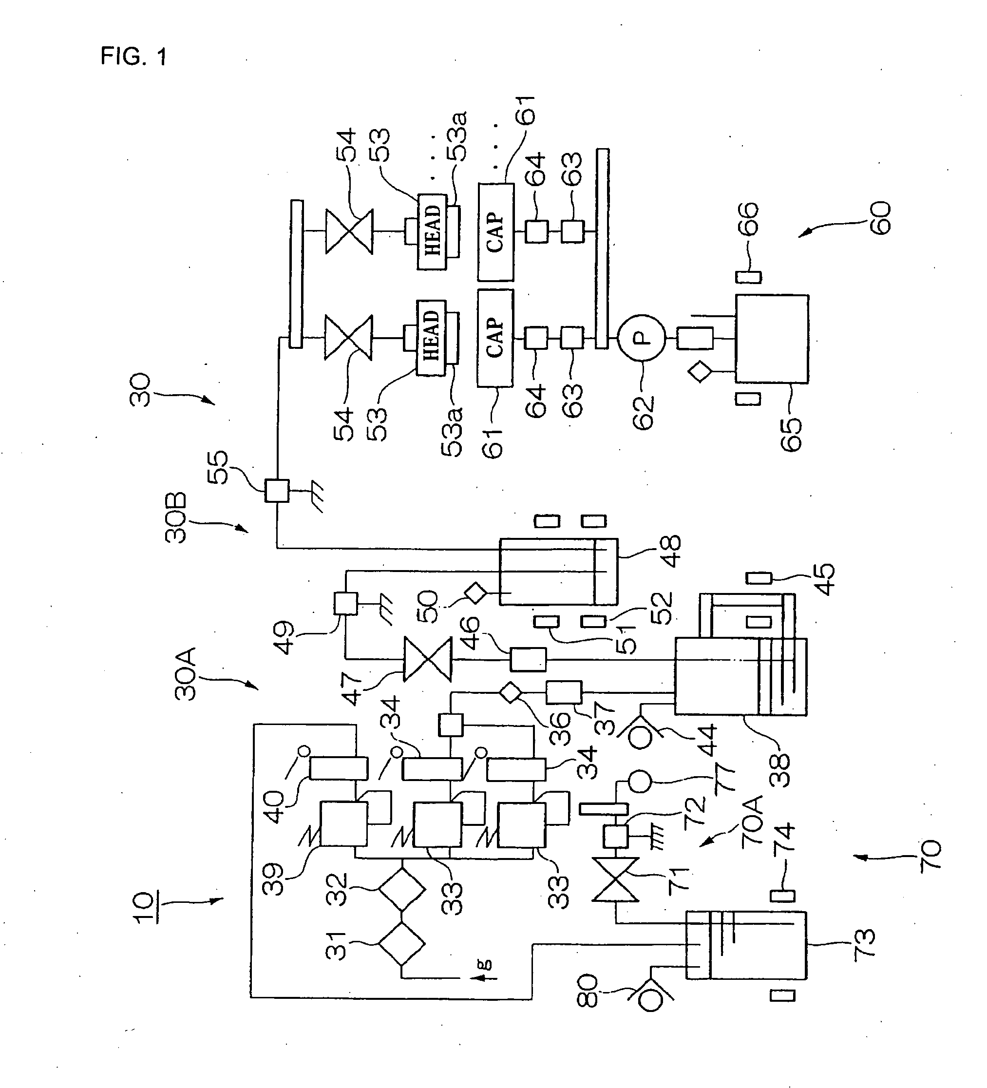
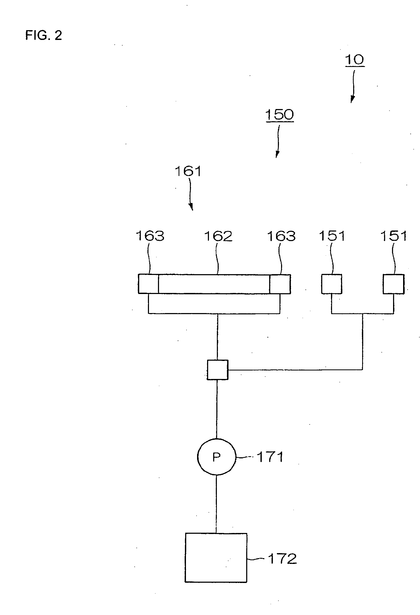
[0036] At first, an embodiment of the droplet ejection device of the invention is explained. FIG. 1 shows a general structural overview of the droplet ejection device in this embodiment, and FIG. 2 is a general structural overview of a missing-dot detection and prevention unit in the droplet ejection device shown in FIG. 1.

[0037] As shown in FIG. 1 and FIG. 2, a droplet ejection device 10 generally can include a droplet ejection unit 30, a cap unit 60, a wiping unit (cleaning means) 70, and a missing-dot detection and prevention unit 150.

[0038] The droplet ejection unit 30 is a unit that ejects an ink droplet “R” from a droplet ejection head 53 and lands the ink droplet at a specified position on a substrate (glass substrate, which is hereinafter called a wafer “Wf”). As shown in FIG. 1, the droplet ejection unit 30 generally comprises: a pressuriz...


PUM


Abstract

Exemplary embodiments can provide a fluid control valve, which reduces or prevents any bubble from being built up in the valve itself so as to protect other hydraulic equipment placed in a downstream side from having any malfunction due to such a bubble, and a droplet ejection device using the fluid control valve. A fluid control valve includes a tank, through which a fluid passes, an inlet port, through which a fluid flows into the tank, an outlet port, through which a fluid flows out of the tank, a valve plug that opens and closes at least one of the inlet port and the outlet port, a coupler connecting part of the inlet port side, which is located in an inlet passage connected to the inlet port, and a coupler connecting part of the outlet port side, which is located in an outlet passage connected to the outlet port. Piping is connected to the coupler connecting part of the inlet port side and the coupler connecting part of the outlet port side, each by using a coupler. An annular element for the purpose of offsetting a shoulder part caused by a difference in flow passage diameter existing between each of the coupler connecting parts of the inlet port side and outlet port side and the corresponding coupler can be placed at each of the coupler connecting part of the inlet port side and the coupler connecting part of the outlet port side.

Description

BACKGROUND OF THE INVENTION [0001] 1. Field of Invention [0002] An exemplary embodiment of the present invention relates to a fluid control valve placed in a piping system by using a coupler and a droplet ejection device that uses the fluid control valve. [0003] 2. Description of Related Art [0004] Various types of valves can be used as a fluid control valve to turn on and off a flow of fluid. For example, one such valve is equipped with a valve seat formed in a flow passage, and a valve plug either attached to, or detached from, the valve seat in order to control turning on and off of a flow of fluid passing through an internal part of the valve (for example, refer to Japanese Unexamined Patent Publication No. 2002-310316). [0005] In such a fluid control valve, each of an inlet side and an outlet side is usually equipped with a coupler. Then, each of the inlet side and outlet side is connected to piping through its coupler to enable control of turning on and off a flow of fluid pas...

Claims


Application Information

Patent Timeline
Patent Type & Authority Applications(United States)
IPC IPC(8): B41J2/175B05C5/00B05C11/10B41J2/165F16K25/04F16K27/00F16K27/02
CPCF16K25/04B05C11/10B41J2/165B41J2/175F16K27/02
Inventor NAKAMURA, SHINICHI
Owner SEIKO EPSON CORP
Learn More