Electrostatic fluid accelerator for and method of controlling a fluid flow

a fluid accelerator and electrostatic technology, applied in the direction of plasma technique, oxygen/ozone/oxide/hydroxide, electric supply techniques, etc., can solve the problems of limited ability to produce a substantial fluid flow suitable for commercial use, increased fluid flow resistance, and inability to use physically large electrodes, etc., to achieve increased fluid velocity, improved fluid flow resistance, and improved power handling capability

Inactive Publication Date: 2005-07-14
TESSERA INC
View PDF18 Cites 22 Cited by
  • Summary
  • Abstract
  • Description
  • Claims
  • Application Information

AI Technical Summary

Benefits of technology

[0018] Still another advantage of an embodiment of the present invention is the use of electrodes using other than solid materials for providing a corona discharge. For example, a conductive fluid may be efficiently employed for the corona discharge emission, supporting greater power handling capabilities and, therefore, in

Problems solved by technology

One of these deficiencies includes a limited ability to produce a substantial fluid flow suitable for commercial use.
Another deficiency is a necessity for large electrode structures (other than the corona electrodes) to avoid generating a high intensity electric field.
Using physically large electrodes further increases fluid flow resistance and limits EFA capacity and efficiency.
Still other problem arises when an EFA operates near or at maximum capacity, i.e., with some maximum voltage applied and power consumed.
In this case, the operational voltage applied is characteristically maintained near a dielectric breakdown voltage such that undesirable electrical events may result such as sparking and/or arcing.
Still a further disadvantage may result if unintended contact is made with one of the electrodes, poten

Method used


Image

  • Electrostatic fluid accelerator for and method of controlling a fluid flow
  • Electrostatic fluid accelerator for and method of controlling a fluid flow
  • Electrostatic fluid accelerator for and method of controlling a fluid flow

Examples


Embodiment Construction

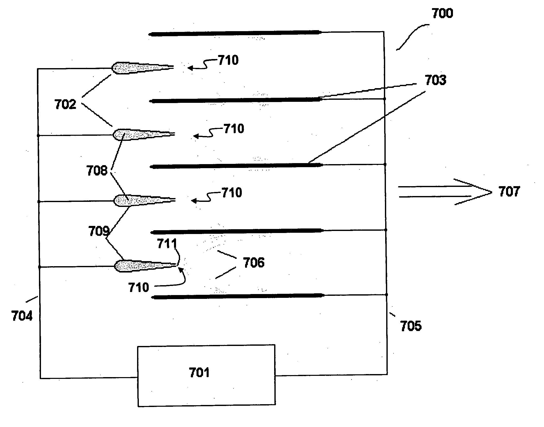
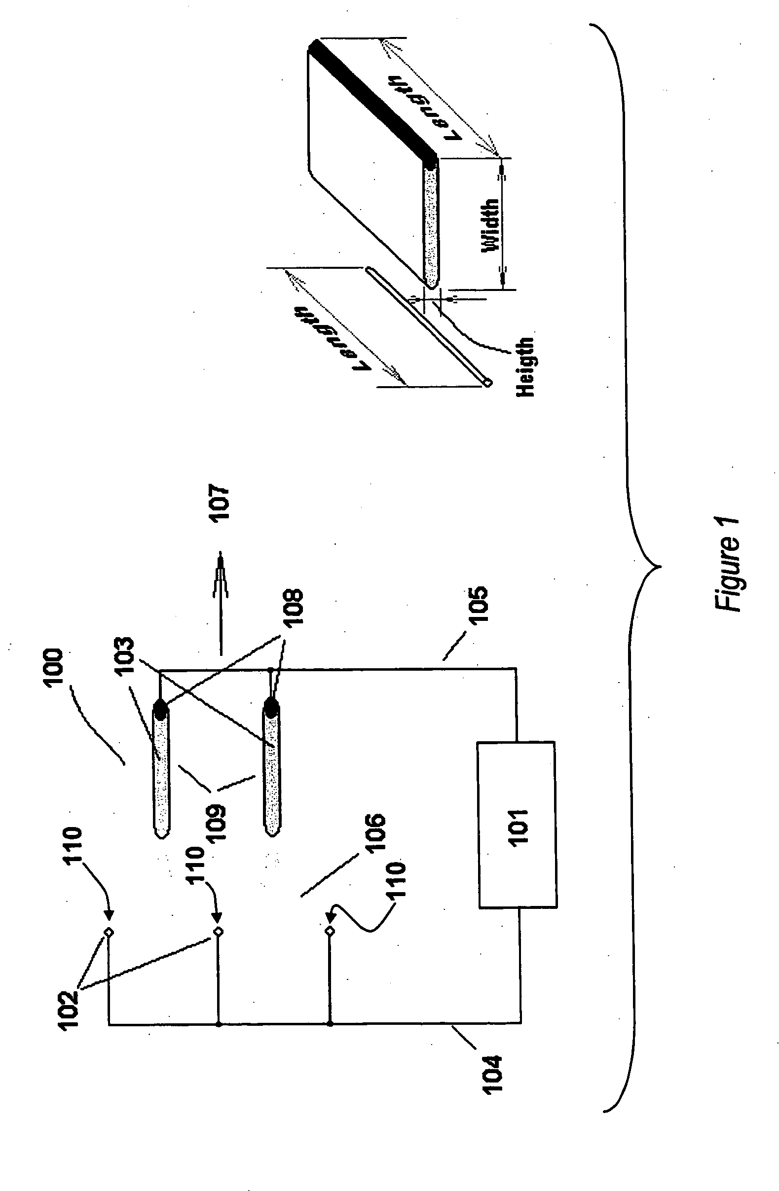
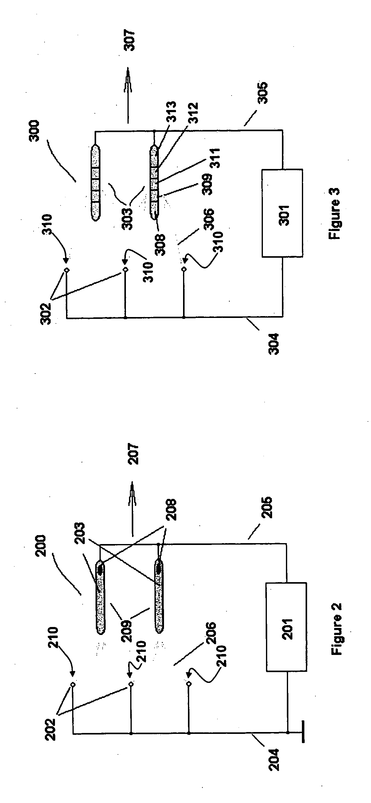
[0027]FIG. 1 is a schematic diagram of EFA device 100 including wire-like corona electrodes 102 (three are shown for purposes of the present example although other numbers may be included, a typical device having ten or hundreds of electrodes in appropriate arrays to provide a desired performance) and accelerating electrodes 109 (two in the present simplified example). Each of the accelerating electrodes 109 includes a relatively high resistance portion 103 and a low resistance portion 108. High resistance portion portions 103 have a specific resistivity ρ within a range of 101 to 109 ′Ω-cm and, more preferably, between 105 and 108 ′Ω-cm with a more preferred range between 106 and 107 ′Ω-cm.

[0028] All the electrodes are shown in cross section. Thus corona electrodes 102 are in the form or shape of thin wires, while accelerating electrodes 109 are in the shape of bars or plates. “Downstream” portions of corona electrodes 102 closest to accelerating electrodes 109 form ionizing edges...


PUM


Abstract

An electrostatic fluid accelerator includes a first number of corona electrodes and a second number of accelerating electrodes spaced apart from and parallel to adjacent ones of the corona electrodes. An electrical power source is connected to supply the corona and accelerating electrodes with an operating voltage to produce a high intensity electric field in an inter-electrode space between the corona electrodes and the accelerating electrodes. The accelerating electrodes may be made of a high electrical resistivity material, each of the electrodes having mutually perpendicular length and height dimension oriented transverse to a desired fluid flow direction and a width dimension oriented parallel to the desired fluid flow direction. A length of the electrodes in a direction transverse to a desired fluid flow direction is greater than a width of the electrodes parallel to the fluid flow direction, and the width of the electrodes is at least ten times a height of the electrodes in a direction transverse to both the desired fluid flow direction and to the length.

Description

BACKGROUND OF THE INVENTION [0001] 1. Field of the Invention [0002] The invention relates to a device for accelerating, and thereby imparting velocity and momentum to a fluid, and particularly to the use of corona discharge technology to generate ions and electrical fields especially through the use of ions and electrical fields for the movement and control of fluids such as air, other fluids, etc. [0003] 2. Description of the Related Art [0004] A number of patents (see, e.g., U.S. Pat. Nos. 4,210,847 by Shannon, et al. and 4,231,766 by Spurgin) describe ion generation using an electrode (termed the “corona electrode”), accelerating and, thereby, accelerating the ions toward another electrode (termed the “accelerating”, “collecting” or “target” electrode), thereby imparting momentum to the ions in a direction toward the accelerating electrode. Collisions between the ions and an intervening fluid, such as surrounding air molecules, transfer the momentum of the ions to the fluid induc...

Claims


Application Information

Patent Timeline
IPC IPC(8): B03C3/68H05H1/24
CPCH05H1/24B03C3/68H05H2242/20H05H1/47
Inventor KRICHTAFOVITCH, IGOR A.
Owner TESSERA INC
Why Eureka
Try Eureka