Surface modified colloidal abrasives, including stable bimetallic surface coated silica sols for chemical mechanical planarization

a technology of colloidal abrasives and surface coatings, which is applied in the direction of polishing compositions, other chemical processes, lapping machines, etc., can solve the problems of reducing the reliability of integrated circuits and contaminating the surface of polished substrates

Active Publication Date: 2005-07-21
VERSUM MATERIALS US LLC
View PDF63 Cites 47 Cited by
  • Summary
  • Abstract
  • Description
  • Claims
  • Application Information

AI Technical Summary

Benefits of technology

[0020] Still further provided is a method for polishing a surface of a substrate, said method comprising applying the composition of the invention to the surface of the substrate to polish the surface of the sub

Problems solved by technology

As a result, the polished substrates can become contaminated by the adsorption of charged species from

Method used


Image

  • Surface modified colloidal abrasives, including stable bimetallic surface coated silica sols for chemical mechanical planarization

Examples


example 1

[0057] Step 1: Preparation of Boron-Modified Silica Sol

[0058] This example describes the preparation of boron surface-modified colloidal silica starting with colloidal silica particles having an average particle diameter of 40 to 55 nanometers.

[0059] Approximately 1 kg of AMBERLITE IR-120 ion exchange resin (Rohm and Haas Company, Philadelphia, Pa.) was washed with 1 liter of 20% sulfuric acid solution. The mixture was stirred and the resin was allowed to settle. The aqueous layer was decanted and washed with 10 liters of deionized water. The mixture was again allowed to settle and then the aqueous layer was decanted. This procedure was repeated until the decanted water was colorless. This procedure afforded an acidic form of resin.

[0060] SYTON® HT 50 (12 kg, approximately 2.27 gallons, DuPont Air Products NanoMaterials L.L.C., Carlsbad, Calif.) was placed in a five-gallon mix tank equipped with an agitator. 2.502 kg of deionized water were added to the tank and the solution was ...

example 2

[0065] Addition of Boric Acid-Iron Nitrate Mixture to Deionized SYTON HT 50

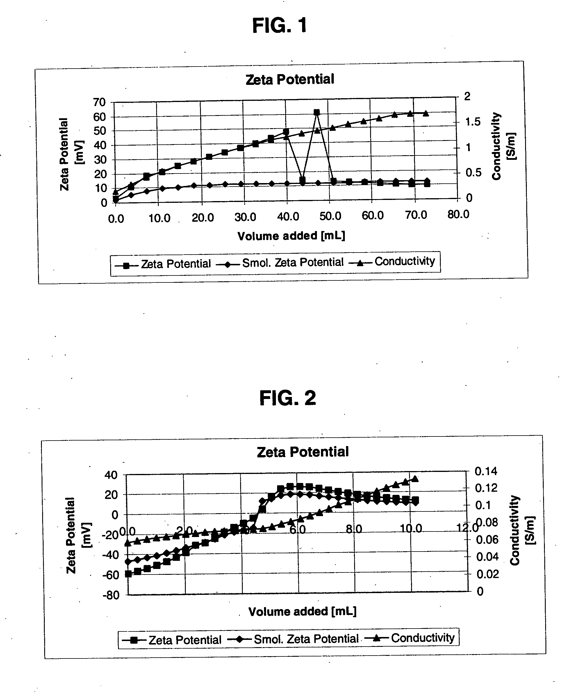
[0066] In this procedure, deionized SYTON HT 50 at pH 2 (600 grams, supplied by DuPont Air Products NanoMaterials L.L.C.), was transferred to a 4-liter beaker. Under agitation, 400 grams of deionized water were added, followed by the addition of a mixture of boric acid (12 grams) and ferric nitrate (10.1 grams). After the addition of boric acid and ferric nitrate, an additional 278 grams of water were added. The mixture was heated between 45 and 50° C. for 2.5 hours. After heating, the mixture was cooled, the molar ratio of iron to silica was 1:2 (0.5), the molar ratio of iron to boric acid was 2:4.3 (0.47), the pH was 1.67, and the zeta potential was +16.4 millivolts. In FIG. 1, the zeta-potential graph shows how zeta-potential changes from the zero or slightly negatively charged surface to the positively charged surface.

example 3

[0067] In this example, Example 2 was repeated using a molar ratio of iron to silica of 1:4 (0.25) and a molar ratio of iron to boric acid of 1:4.3 (0.23). The pH of the surface modified was 2.11, and the zeta potential was +25.2 millivolts. This example shows that the pH and zeta potential can be controlled by changing the concentration of ferric nitrate or boric acid.


PUM

PropertyMeasurementUnit
Solubility (mass)aaaaaaaaaa
Abrasiveaaaaaaaaaa
Selectivityaaaaaaaaaa

Abstract

A composition and an associated method for chemical mechanical planarization (or other polishing) are described. The composition includes a surface-modified abrasive modified with at least one stabilizer and at least one catalyst differing from the at least one stabilizer. The composition can further include a medium containing the abrasive and an oxidizing agent (e.g., hydrogen peroxide), wherein the at least one catalyst is adapted to catalyze oxidation of a substrate by the oxidizing agent. Preferably, the abrasive is alumina, titania, zirconia, germania, silica, ceria and/or mixtures thereof, the stabilizer is B, W and/or Al, and the catalyst is Cu, Fe, Mn, Ti, W and/or V. Both the stabilizer and the catalyst are immobilized on the abrasive surface. The method includes applying the composition to a substrate to be polished, such as substrates containing W, Cu and/or dielectrics.

Description

BACKGROUND OF THE INVENTION [0001] The present invention pertains to surface-modified colloidal abrasive polishing compositions and associated methods of using these compositions, particularly for chemical mechanical planarization (CMP, also known as chemical mechanical polishing). [0002] CMP is now widely known to those skilled in the art and has been described in numerous patents and open literature publications. Some introductory references on CMP are as follows: “Polishing Surfaces for Integrated Circuits”, by B. L. Mueller and J. S. Steckenrider, Chemtech, February, 1998, pp. 38-46; and H. Landis et al., Thin Solids Films, 220 (1992), p. 1. [0003] In a typical CMP process, a substrate (e.g., a wafer) is placed in contact with a rotating polishing pad attached to a platen. A CMP slurry, typically an abrasive and chemically reactive mixture, is supplied to the pad during CMP processing of the substrate. During the CMP process, the pad (fixed to the platen) and substrate are rotat...

Claims


Application Information

Patent Timeline
IPC IPC(8): B24B37/04B24D3/02C09G1/02C09K3/14H01L21/321
CPCB24B37/044C09G1/02H01L21/3212C09K3/1463C23F3/04C09K3/1409
Inventor SIDDIQUI, JUNAID AHMED
Owner VERSUM MATERIALS US LLC
Why Eureka
Try Eureka