Dehumidifying element and manufacturing method for the same

a technology of dehumidifying element and manufacturing method, which is applied in the direction of heating types, other chemical processes, separation processes, etc., can solve the problems of limited moisture content of supply air for being dehumidified, deterioration of dehumidifying characteristics of elements during use, and limited sorption capacity of elements, etc., to achieve high humidity absorption rate

a technology of dehumidifying element and manufacturing method, which is applied in the direction of heating types, other chemical processes, separation processes, etc., can solve the problems of limited moisture content of supply air for being dehumidified, deterioration of dehumidifying characteristics of elements during use, and limited sorption capacity of elements, etc., to achieve high humidity absorption rate

US20050155491A1Inactive Publication Date: 2005-07-21KOREA INST OF SCI & TECH

Image

  • Dehumidifying element and manufacturing method for the same
  • Dehumidifying element and manufacturing method for the same
  • Dehumidifying element and manufacturing method for the same

Examples


embodiment

Preferred Embodiment

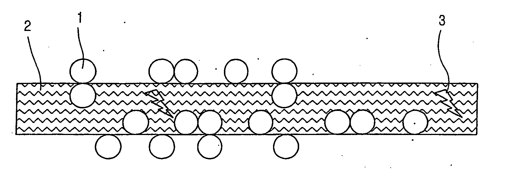
[0039]FIG. 1 is a longitudinal sectional view of the dehumidifying element according to the present invention.

[0040] As shown in FIG. 1, the dehumidifying element of the present invention is composed of a porous carrier 2 to the surface or the inside of which SAP is attached. The SAP is formed in the porous carrier or at a surface thereof as granular particles 1.

[0041] The granular particles 1 include the SAP, and the SAP is contacted to a hygroscopic base (not shown). At this time, the carrier 2 consists of fiber composed of natural or composite polymer and a filament. Further, the carrier 2 includes fibers 3 containing the SAP therein, in which the fibers 3 are inserted into the porous carrier 2. The fibers 3 are contacted to the hygroscopic base in a finely distributed form like the granules 1, and can be applied to a surface of the porous carrier 2.

[0042] A particle diameter of the granules 1 is approximately identical for all granular particles and is in ...


PUM

PropertyMeasurementUnit
particle diameteraaaaaaaaaa
temperatureaaaaaaaaaa
particle diameteraaaaaaaaaa

Abstract

A dehumidifying element includes a super absorbing polymer (SAP), and a hygroscopic base, thereby maintaining hygroscopic characteristics regardless of aging and a high humidity absorbing rate and needing a smaller amount of energy for regeneration.

Description

TECHNICAL FIELD [0001] The present invention relates to a dehumidifying element and a manufacturing method for the same. BACKGROUND ART [0002] A humidity exchanger element dehumidifies gas by a reaction between a base and silicate aerogel such as aluminum oxide-silicate or titanium silicate / titanium-aluminum silicate. [0003] According to U.S. Pat. No. 5,505,769, the elements can be included in a sheet composed of inorganic fiber, or can be included in a device formed by the sheet. [0004] However, the regeneration of the humidity exchanger element needs an increased regeneration temperature (approximately 90˜150° C.). A sorption capacity of the element is limited and has high pressure loss, and moisture of content of supply air for being dehumidified is limited. Also, a sorption capacity of the humidity exchanger element is decreased over time, that is, the element is greatly influenced by aging. [0005] Also, nucleus and bio-film are formed while the element dehumidifies, thereby clo...

Claims


Application Information

Patent Timeline
21 Jul 2005
Publication
US20050155491A1
IPC
B01D53/28; B01J20/04; B01J20/22; B01J20/26; B01J20/28
CPC
B01D53/28; B01J20/046; B01J20/28023; B01J20/28028; B01J20/2803; B01J20/28033; B01J20/2804; B01J20/28045
Inventors
FAUST, STEPHAN; FALK, GUIDO