Methods and devices for charge management for three-dimensional and color sensing

a three-dimensional and color sensing technology, applied in the field of three-dimensional and color sensing charge management, can solve the problems of difficult to approximate the focal distance to an object or subject, time-consuming process, and inability to work well with luminosity-based systems, so as to achieve effective color resolution of a camera or sensor according, improve detection signal characteristics, and reduce overhead

Inactive Publication Date: 2005-07-21
MICROSOFT TECH LICENSING LLC
View PDF44 Cites 33 Cited by
  • Summary
  • Abstract
  • Description
  • Claims
  • Application Information

AI Technical Summary

Benefits of technology

[0020] In applicants' referenced '740 patent and indeed the '496 patent, the described system transmitted high frequency component periodic signals having low average power and low peak power, e.g., tens of mW rather than watts. For ease of analysis, optical energy periodic signals such as an ideal sinusoid waveform, e.g., cos(ω·t), were assumed, and will be assumed herein. Emitting such low peak power high frequency component periodic signals permitted use of inexpensive light sources and simpler, narrower bandwidth pixel detectors. Bandwidths could be on the order of a few hundred KHz with an operating (emitted energy modulation) frequency of about 200 MHz. Good resolution accuracy was still obtainable using a low peak power optical emitter in that the effective duty cycle is greater than the output from a narrow-pulsed optical emitter of higher peak power.
[0023] Distance z is known modulo 2πC / (2·ω)=C / (2·f). If desired, several different modulation frequencies of optically emitted energy may be used, e.g., f1, f2, f3 . . . , to determine z modulo C / (2·f1), C / (2·f2), C / (2·f3). The use of multiple different modulation frequencies advantageously can reduce aliasing. If f1, f2, f3 are integers, aliasing is reduced to the least common multiplier of f1, f2, f3, denoted LCM(f1, f2, f3). If f1, f2, f3 are not integers, they preferably are modeled as fractions expressible as a1 / D, a2 / D, and a3 / D, where I in ai is an integer, and D=(GCD) represents the greatest common divisor of a1, a2, a3. From the above, distance z may be determined modulo LCM(a1, a2, a3) / D. This same analytical approach is also practiced with the various embodiments of the present invention, described later herein.
[0026] In applicants' '740 and '496 patents, detection sensitivity for such systems was enhanced even while using low peak power high frequency component periodic signals, with phase delay used to determine TOF, dz / dt (and / or dx / dt, dy / dt, and other information. More specifically, an improved mixer was described, in which mixing results from modulating quantum efficiency (QE) of the photodiodes in the detector array, for example through use of a MOS transistor gate or altering reverse bias of the photodiodes. Such mixing offered many advantages including improved high frequency sensitivity, improved detection signal / noise, smaller form factor, lower power consumption, and less cost to fabricate.
[0030] Using fixed phase delay (FPD or category two) fixed homodyne signals were used to QE modulate each photodetector. In category two, different groups or banks of photodiode detectors could be defined in a non-localized manner within the array. For example, a first bank of photodiode detectors may be QE modulated with fixed 0° phase shift, a second bank may be QE modulated with fixed 90° phase, shift, a third bank with fixed 180° phase shift, and a fourth bank with fixed 270° phase shift. Within each pixel, there may be photodiode detectors that correspond to every one of the four banks. Phase information and target object brightness information can be determined by examining output values for each bank within a pixel. This FPD approach simplified the electronic circuitry associated with each pixel, reduced power consumption, and could reduce IC chip area requirement, and enabled a range of techniques for temporal and spatial multiplexing including so-called tessellation.
[0033] In applicants' provisional patent application Ser. No. 60 / 400,002, electrically wavelength programmable CMOS color sensors are disclosed. These structures may be similar to structures disclosed in the '422 application and indeed applicants are able to use the same structures to accomplish both TOF and color detection functions with minimal overhead. Such detection sensors make use of the fact that incoming light of different wavelengths reaches different depths within the silicon substrate of a CMOS sensor. Applicants vary magnitude of the potential applied to a polysilicon gate in the sensor structure to dynamically alter the color detection characteristics of the detector structure. The resultant detector can resolve a vast number of colors without using color filters. Unlike prior art color camera sensors in which a pixel captures but a single color, each pixel according to the '002 application can determine the spectral composition (e.g., complex color) of light. Thus for a given number of total pixels, the effective color resolution of a camera or sensor according to the '002 application is substantially higher than with a prior art color camera. Further the color sensor resolves color without limitation as to human color perception. A prior art color camera or sensor cannot distinguish between a surface reflecting yellow, and a surface that reflects both red and green, because information is lost when such camera maps a color into its red, green, and blue constituents. But a color camera or pixel sensor according to the '002 invention can determine the complex spectral composition of light at each pixel, and thus can discriminate between an image that reflects yellow, and an image the reflects both red and green.
[0034] In the various embodiments of the present invention, on-chip measurement information may be output in random rather than sequential order, and on-chip signal processing for object tracking and other information requiring a three-dimensional image can be readily accomplished. The overall system is small, robust, requires relatively few off-chip discrete components, and exhibits improved detection signal characteristics. On-chip circuitry can use such TOF data to readily simultaneously measure distance and velocity of all points on an object or all objects in a scene. Similarly, the on-chip circuitry can also determine spectral composition of the detected image at each pixel in the detection sensor. Advantageously a sensor whose individual pixels can determine spectral composition can also be used to determined TOF information.

Problems solved by technology

For example, if a CCD range finder system were used in a digital zoom lens application, even though most of the relevant data would be provided by a few of the CCDs in the array, it would nonetheless be necessary to readout the entire array to gain access to the relevant data, a time consuming process.
But in general, luminosity-based systems do not work well.
In a complicated scene, it can be very difficult to approximate the focal distance to an object or subject standing against a background using change in luminosity to distinguish the subject from the background.
Unfortunately, reflected luminosity data does not provide a truly accurate rendering of distance because the reflectivity of the object is unknown.
At best these prior art focus systems can focus a lens onto a single object in a field of view, but cannot simultaneously measure distance for all objects in the field of view.
However it is challenging for a computer program to judge object distance from a stereoscopic image.
Errors are often present, and the required signal processing requires specialized hardware and computation.
But in practice it is difficult to accurately extract distance and velocity data along a viewing axis from luminosity measurements.
The necessary distance measurements may be erroneous due to varying lighting conditions and other shortcomings noted above.
Although specialized three dimensional imaging systems exist in the nuclear magnetic resonance and scanning laser tomography fields, such systems require substantial equipment expenditures.
Further, these systems are obtrusive, and are dedicated to specific tasks, e.g., imaging internal body organs.
Understandably having to provide precision moving mechanical parts add bulk, complexity, and cost to such range finding system.
Further, because these systems sample each pixel sequentially, the number of complete image frames that can be sampled per unit time is limited.

Method used


Image

  • Methods and devices for charge management for three-dimensional and color sensing
  • Methods and devices for charge management for three-dimensional and color sensing
  • Methods and devices for charge management for three-dimensional and color sensing

Examples


Embodiment Construction

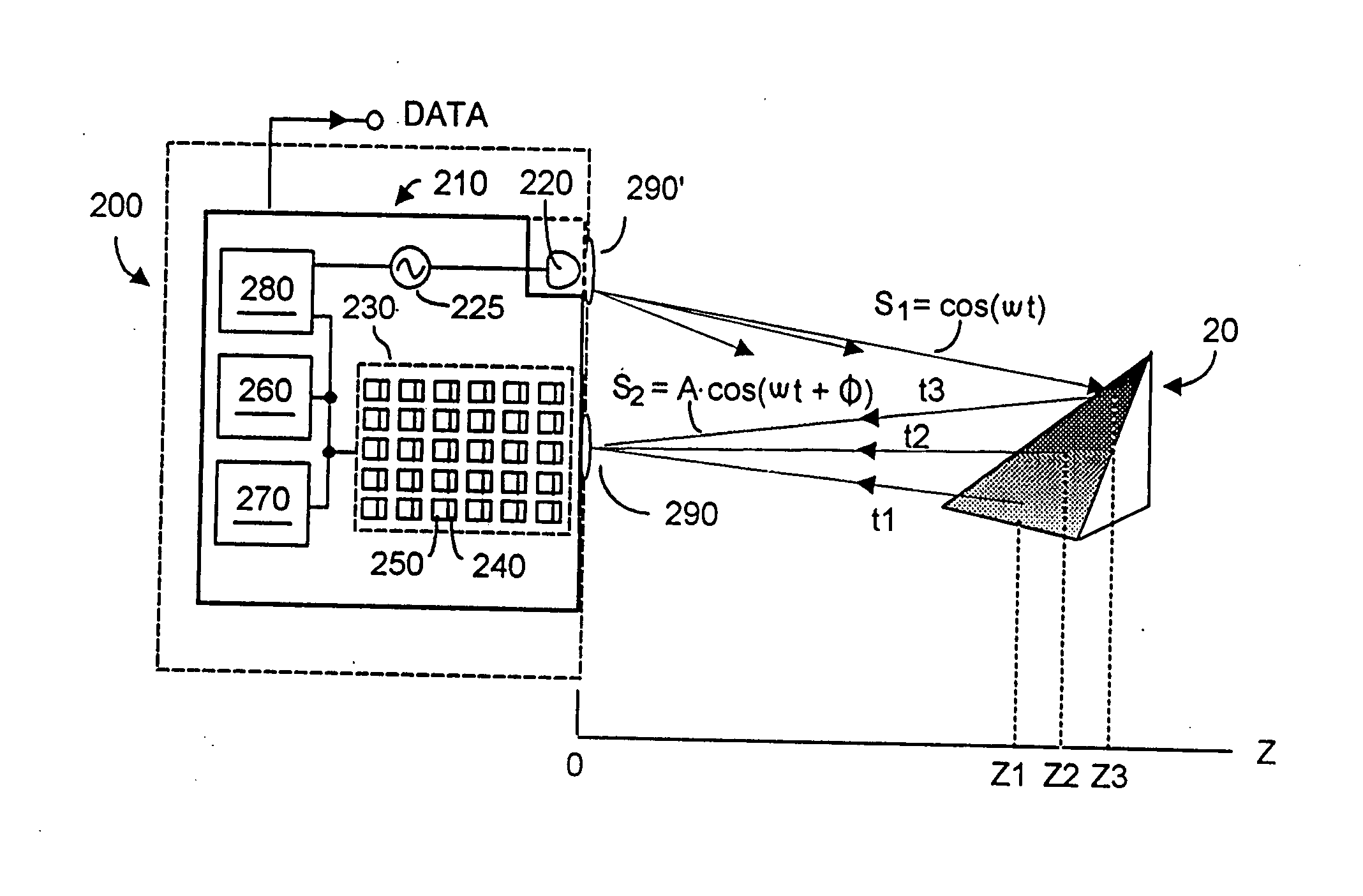
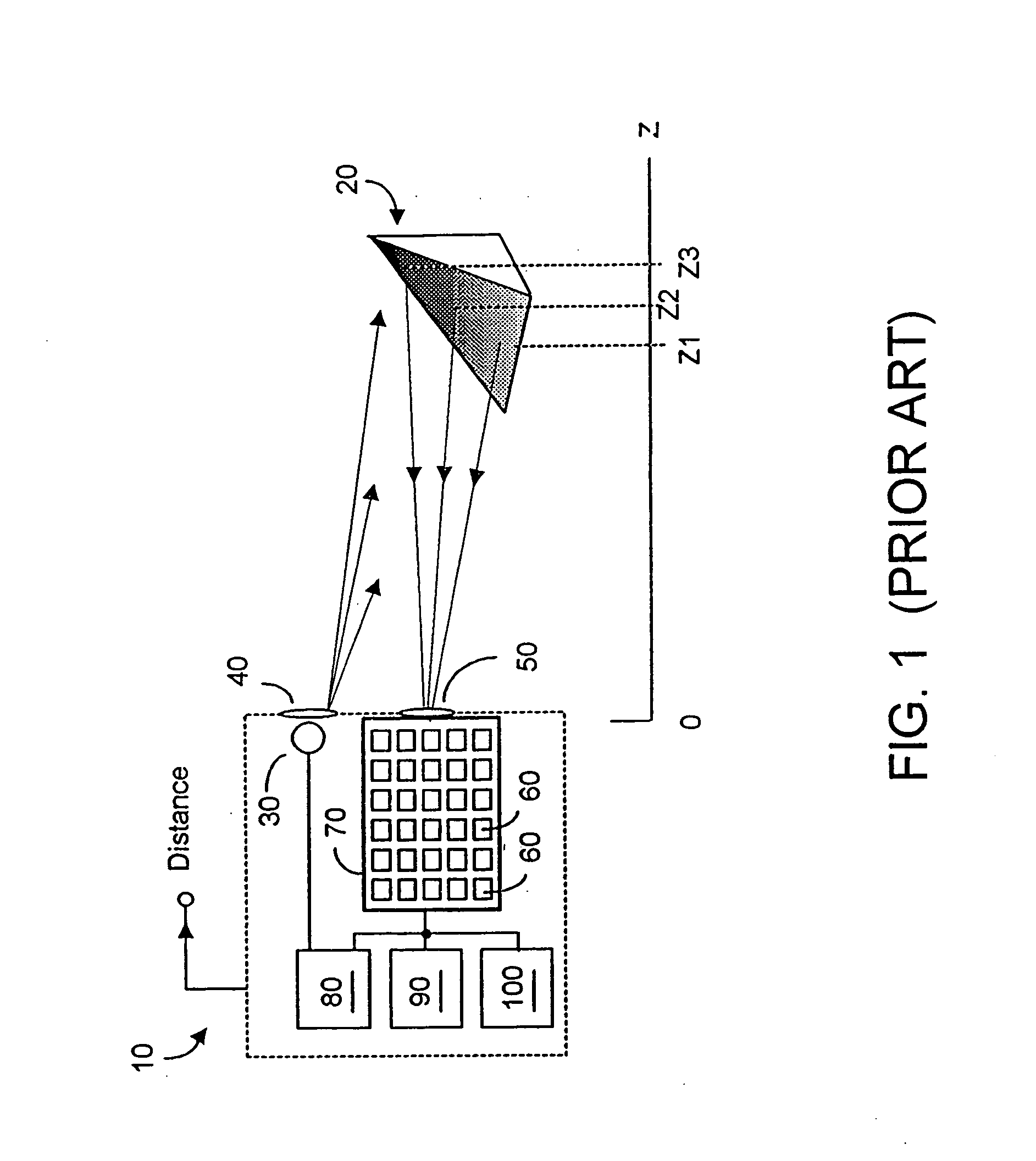
[0091] Before describing the inventions set forth in the three referenced provisional patent applications, it may be useful to first describe the invention(s) of U.S. Pat. No. 6,580,496, hereafter “the '496 invention” or U.S. Pat. No. 6,515,740. As the '496 and '740 patents had the same specification, reference to the inventions of either will be denoted herein as being to the '496 invention.

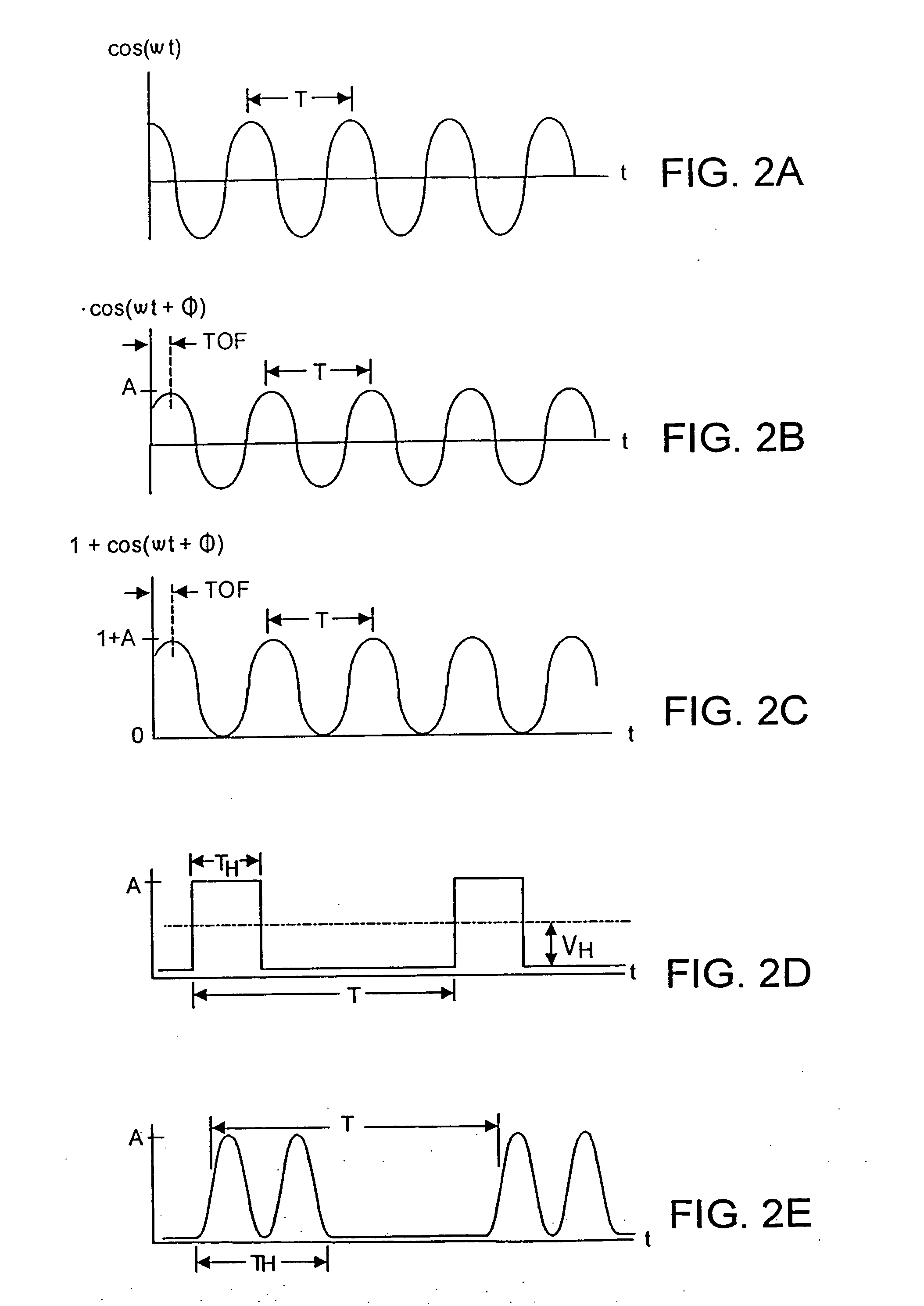
[0092] That invention advantageously transmitted and detected optical energy that was periodic with a high frequency component, and relied upon phase shift between transmitted and detected waveforms to discern time-of-flight (TOF) and thus z-distance data. Although pulsed-type periodic waveforms could be used, the '496 invention will be described with respect to the emission and detection of sinusoidal waveforms, as such waveforms are rather easily analyzed mathematically. However it is to be understood that periodic pulsed waveforms with a high frequency component including imperfect sinusoida...


PUM

PropertyMeasurementUnit
frequencyaaaaaaaaaa
wavelengthaaaaaaaaaa

Abstract

Structures and methods for three-dimensional image sensing using high frequency modulation includes CMOS-implementable sensor structures using differential charge transfer, including such sensors enabling rapid horizontal and slower vertical dimension local charge collection. Wavelength response of such sensors can be altered dynamically by varying gate potentials. Methods for producing such sensor structures on conventional CMOS fabrication facilities include use of “rich” instructions to command the fabrication process to optimize image sensor rather than digital or analog ICs. One detector structure has closely spaced-apart, elongated finger-like structures that rapidly collect charge in the spaced-apart direction and then move collected charge less rapidly in the elongated direction. Detector response is substantially independent of the collection rate in the elongated direction.

Description

RELATION TO PREVIOUSLY FILED APPLICATIONS [0001] This is a continuation-in-part application from co-pending U.S. patent application Ser. No. 10 / 020,339 (“the '339 application”), filed 11 Dec. 2001 entitled “Systems for CMOS-Compatible Three-Dimensional Image Sensing Using Quantum Efficiency Modulation” filed in the name of Bamji, et al. and assigned to Canesta, Inc., San Jose, Calif., which application is now U.S. Pat. No. 6,580,496 (2003). The '339 application claimed priority from U.S. provisional applications Ser. No. 60 / 254,873 (filed 11 Dec. 2000) and Ser. No. 60 / 247,158 (filed 9 Nov. 2000). [0002] Priority herein is also claimed from co-pending U.S. provisional patent application Ser. No. 60 / 393,408 filed in the names of Liu and Bamji on 1 Jul. 2002 entitled “3D Sensing Using Differential Charge Transfer Method”, also assigned to Canesta, Inc., from co-pending U.S. provisional patent application Ser. No. 60 / 396,422 filed in the names of Bamji and Liu on 15 Jul. 2002 entitled “...

Claims


Application Information

Patent Timeline
Patent Type & Authority Applications(United States)
IPC IPC(8): A61B6/00A61N5/00G01B11/26G01C3/00G01N23/00G01S7/4914G01S7/493G01S17/08G01S17/36G01S17/894G21G5/00G21K1/12H01LH01L27/146H01L31/02H04N3/14H05G1/60
CPCG01C3/00G01J3/50G01S7/493G01S17/36G01S7/4914H01L27/14601H01L27/14645H01L31/02024H01L31/1133G01S17/89G01S17/894
Inventor BAMJI, CYRUSLIU, XINQIAO
Owner MICROSOFT TECH LICENSING LLC
Why Eureka
Try Eureka