Piezoelectric o-ring transducer

a technology of o-ring transducer and piezoelectric ring, which is applied in the direction of generator/motor, engine components, mechanical equipment, etc., to achieve the effect of increasing system utilization

Inactive Publication Date: 2005-07-21
TAIWAN SEMICON MFG CO LTD
View PDF13 Cites 32 Cited by
  • Summary
  • Abstract
  • Description
  • Claims
  • Application Information

AI Technical Summary

Benefits of technology

[0008] Accordingly, the primary object of the present invention is to advance the state of the art of immediately identifing o-ring failure in reaction chambers.
[0009] It is another object of the present invention to indicate where a defective o-ring is located, thereby eliminating the otherwise length...

Problems solved by technology

That is to say, seal reliability is of major concern since undetected seal damage ma...

Method used


Image

  • Piezoelectric o-ring transducer
  • Piezoelectric o-ring transducer
  • Piezoelectric o-ring transducer

Examples


Embodiment Construction

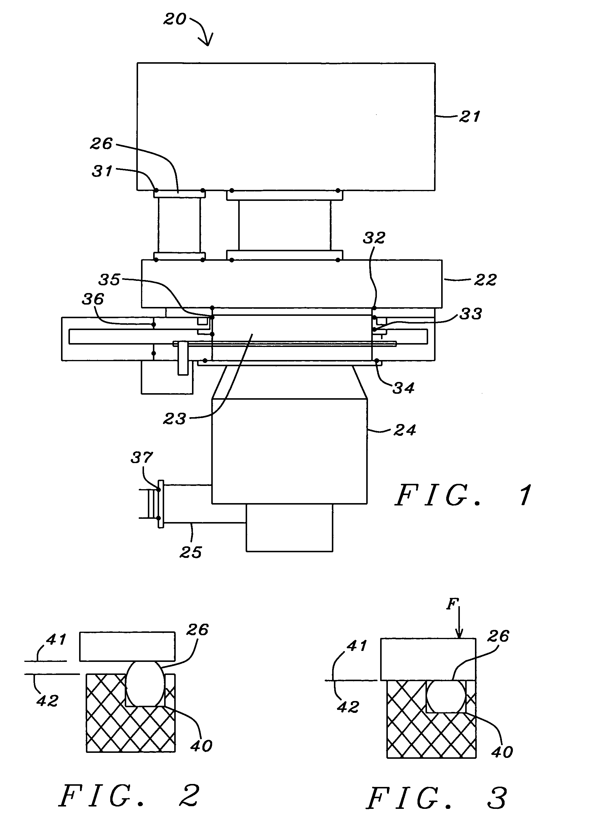
[0025]FIG. 1 schematically illustrates a vacuum system 20 intended for operation in the 10−6 to 10−9 Torr pressure range. A process chamber 21 in which materials for a metal deposition process using titanium, titanium nitride, or aluminum copper alloys, etc. These processes are performed at low operating pressure (less than 10−6 Torr) to maximize film density and deposition rate.

[0026] Several of the major components involved in a system of this type include, a process chamber 21, an exhaust manifold 22, mechanical and diffusion pumps (not shown) communicating to fore line 25, a turbomolecular pump 24, and many flanged surfaces 26 with seals 31 between mechanically interlocked components. Several of the variety of seals that are used are of various diameters and cross-section size o-rings with a variety of names that consists of a bonnet seal 36, an o-ring seal 32 between an advanced process chamber 23 and the exhaust manifold 22, another o-ring seal 35 and a seal 33 for a lower ga...


PUM


Abstract

An o-ring sealing device, molded with an imbedded piezoelectric element, for use in vacuum systems. The imbedded element, of a circumferential length, has an oblong cross-sectional shape, the oblong shape having a pair of ends for externally connecting to a signal processor. The piezoelectric element is concentrically disposed and centrally placed within a mold cavity of a predetermined diameter. The cavity is filled with an elastic material fully encapsulating and insulating the piezoelectric element.

Description

BACKGROUND OF THE INVENTION [0001] 1. Technical Field [0002] This invention relates to the field of very high and ultra high vacuum systems, for example, vacuum systems used in semiconductor manufacturing. More specifically, the invention pertains to the field of vacuum seals and methods to detect seal damage. [0003] 2. Description of the Prior Art [0004] A number of processes are used for depositing or removing thin film material from a semiconductor substrate. Typically, these processes occur in an etching or deposition chamber under a state of very high or ultra high vacuum. The chamber contains a highly reactive environment such as produced in a chemical deposition reaction between a carrier gas and a precursor, producing a solid reaction product. [0005] In spite of rather large differences among various vacuum systems, all of them possess some elements in common. FIG. 1 shows a very high vacuum system device intended for operation in the 10−6 to 10−9 Torr pressure range. The ac...

Claims


Application Information

Patent Timeline
IPC IPC(8): F16J15/06F16J15/32H01L21/00H01L41/08H01L41/113
CPCF16J15/064H01L41/1132F16J15/32H10N30/302
Inventor TSENG, MING-HUNGCHEN, CHIN-CHIHWANG, TZU-CHANTIEN, WEI-SHIN
Owner TAIWAN SEMICON MFG CO LTD
Why Eureka
Try Eureka