Connector and Coaxial Cable with Outer Conductor Cylindrical Section Axial Compression Connection

Inactive Publication Date: 2005-07-21
ANDREW CORP
View PDF17 Cites 47 Cited by
  • Summary
  • Abstract
  • Description
  • Claims
  • Application Information

AI Technical Summary

Problems solved by technology

Smooth wall cable has the lowest materials cost but is relatively inflexible, limiting use of smooth wall cable where other than straight cable runs are required.
The mechanical clamp assemblies are relatively expensive, frequently requiring complex manufacturing operations, precision threaded surfaces and or multiple sealing gaskets.
Prior soldered connectors create an interconnection that is difficult to prepare with consistent quality and even when optimally prepared results in an interconnection with limited mechanical strength.
Further, heat from the soldering process may damage cable dielectric and or sheathing material.
Crimping braided outer conductors is more

Method used


Image

  • Connector and Coaxial Cable with Outer Conductor Cylindrical Section Axial Compression Connection
  • Connector and Coaxial Cable with Outer Conductor Cylindrical Section Axial Compression Connection
  • Connector and Coaxial Cable with Outer Conductor Cylindrical Section Axial Compression Connection

Examples


first embodiment

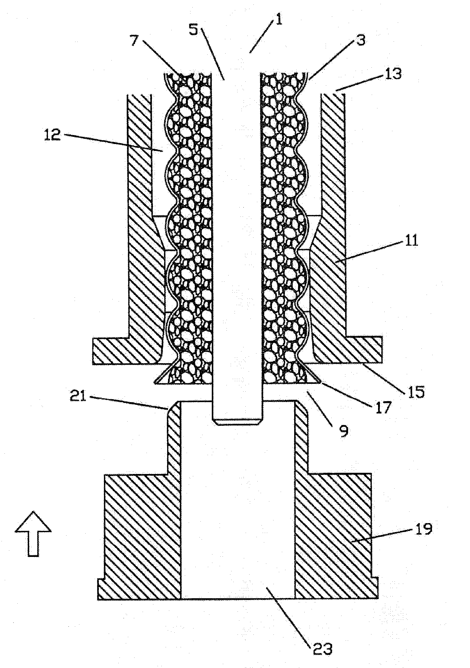
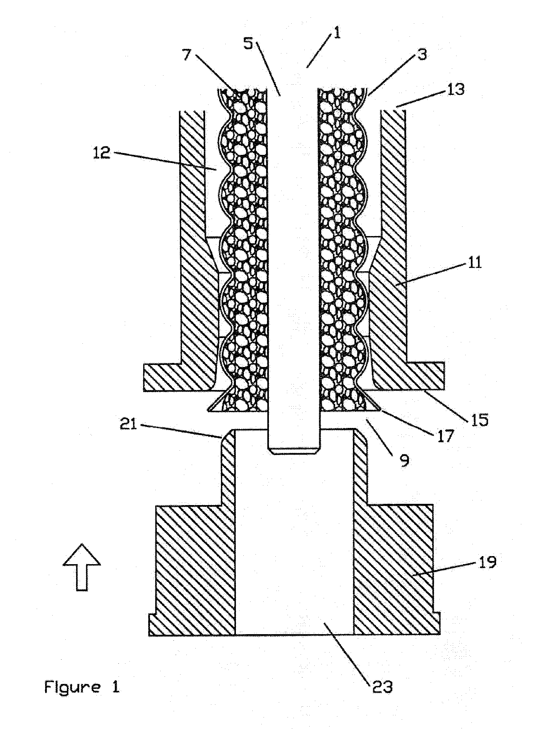
[0020] the invention is shown in FIGS. 1 and 2. A typical annular corrugated coaxial transmission line cable suitable for use with the invention is LDF4 manufactured by the assignee of the invention, Andrew Corporation of Orland Park, Ill. The cable 1 has an outer conductor 3 with annular corrugations and an inner conductor 5 surrounded by dielectric material 7. Prepared for axial compression, any outer protective sheath of the coaxial cable 1 is stripped back and the cable end 9 inserted through a sleeve 11. The sleeve 11 may be configured with a sleeve bore 12 having a wider sleeve cable end 13 diameter that transitions to a sleeve connector end 15 diameter which extends to the sleeve connector end 15. The sleeve cable end 13 diameter may be, for example, adapted to accept insertion of the cable 1 with the outer protective sheath in place. The sleeve connector end 15 diameter is only slightly larger than the diameter of the outer conductor 3, allowing insertion of the outer conduc...

second embodiment

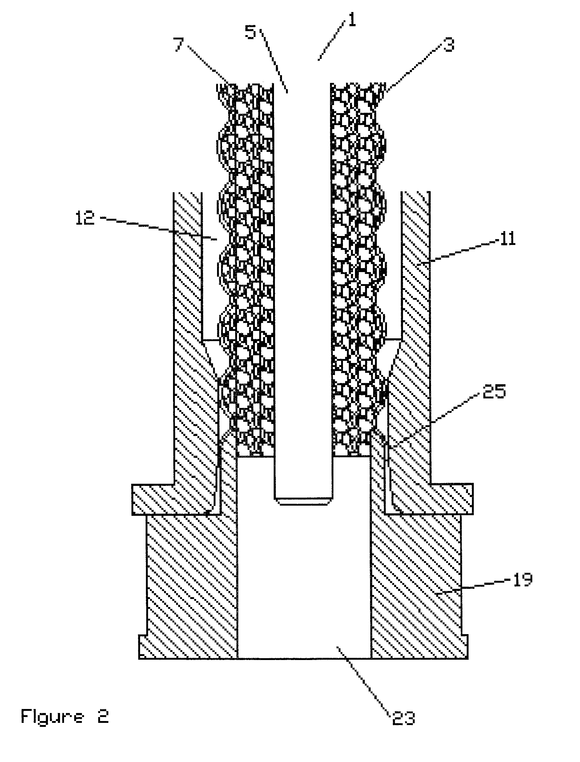
[0024] In the invention, axial compression is similarly applied but flaring and drawing of the outer conductor 3 into a cylindrical section 25 is avoided by forming the coaxial cable 3 with extended cylindrical section(s) 25 at each corrugation peak.

[0025] As shown by the cable 1 used with the first embodiment (FIGS. 1 and 2), the sinusoidal form of annular corrugations common in prior coaxial cables have a roughly equal dimension at the peak of the corrugations compared to the bottom corrugation dimension. As shown in FIG. 3, the cylindrical section(s) 25 of the novel cable 1 according to the invention have a length of at least four times that of the corresponding corrugation bottom, depending on the overall cable dimensions. Preferably, the cylindrical section is formed with a ten to one peak corrugation width to bottom corrugation width or at least a three millimeter corrugation peak cylindrical section 25.

[0026] As the length of each cylindrical section 25 is extended, the cabl...


PUM

PropertyMeasurementUnit
Diameteraaaaaaaaaa

Abstract

A connector and coaxial cable interconnectable via axial compression upon a cylindrical section of a solid outer conductor of the cable. The cylindrical section may be formed in the cable by drawing a cable end into an interference fit between a sleeve and an outer conductor seat formed in the connector body. Alternatively, the cylindrical section may be formed in the outer conductor during cable manufacture and the cylindrical section retained between the outer conductor seat and a crimp ring radially deformed by an angled die face during axial compression. To increase flexibility of a straight walled cable, annular corrugations may be formed in the solid outer conductor with the cylindrical sections at each corrugation peak. The cylindrical section having a length of at least 3 millimeters or 4 times the corrugation depth.

Description

BACKGROUND OF THE INVENTION [0001] 1. Field of the Invention [0002] The invention relates to connectors for coaxial cable. More particularly the invention relates to cost effective connectors and a coaxial cable adapted for interconnection using axial compression along a cylindrical section formed at a peak of annular corrugation(s) in the outer conductor of the coaxial cable. [0003] 2. Description of Related Art [0004] Transmission line cables employing solid outer conductors have improved performance compared to cables with other types of outer conductors such as metallic braid, foil, etc. Solid outer conductor coaxial cables are available in various forms such as smooth wall, annular corrugated, and helical corrugated. Smooth wall cable has the lowest materials cost but is relatively inflexible, limiting use of smooth wall cable where other than straight cable runs are required. Helical cable is flexible and relatively easy to securely terminate via connectors that thread into th...

Claims


Application Information

Patent Timeline
IPC IPC(8): H01R13/646H01R9/05
CPCH01R24/564Y10T29/49204Y10S439/936H01R2103/00H01R9/05
Inventor HARWATH, FRANKNUDD, HUGHTHORBURN, NEIL
Owner ANDREW CORP
Why Eureka
Try Eureka