System and method for a three-axis MEMS accelerometer

a three-axis accelerometer and accelerometer technology, applied in the field of micro electro mechanical systems, semiconductor devices, vibration sensors and inclinometers, can solve the problems of limiting market growth, affecting the use of non-standard initial materials, and few known mems accelerometers, so as to minimize cross-axis sensitivity and reduce the cost of functional testing , the effect of simplifying the extraction of offsets and sensitivities

Inactive Publication Date: 2005-07-28
VAGANOV VLADIMIR +1
View PDF8 Cites 100 Cited by
  • Summary
  • Abstract
  • Description
  • Claims
  • Application Information

AI Technical Summary

Benefits of technology

[0041] Wafer-level bonding of a sensor wafer with cap wafers is a first level of packaging, namely, wafer-level packaging. Wafer-level packaging provides protection of the three-axis accelerometer mechanical structure on overload, mechanical contacts with surrounding objects, from contamination, moisture, etc.
[0042] Functional testing of the three-axis MEMS accelerometer is, preferably, done both on the wafer level and after assembly and packaging. Functional testing at the wafer level is an important step toward low-cost product because it al...

Problems solved by technology

Furthermore, there are only few known MEMS accelerometers that can measure all three components of an acceleration vector, three-axis accelerometers and 3D accelerometers.
However, these markets require low-cost, stable and reliable three-axis accelerometers, which have impeded market growth because of their high cost.
Use of non-standard initial material is undesirable in high-volume production for reasons including: high cost of initial material, additional processing steps in fabrication, limited number of suppl...

Method used


Image

  • System and method for a three-axis MEMS accelerometer
  • System and method for a three-axis MEMS accelerometer
  • System and method for a three-axis MEMS accelerometer

Examples


third embodiment

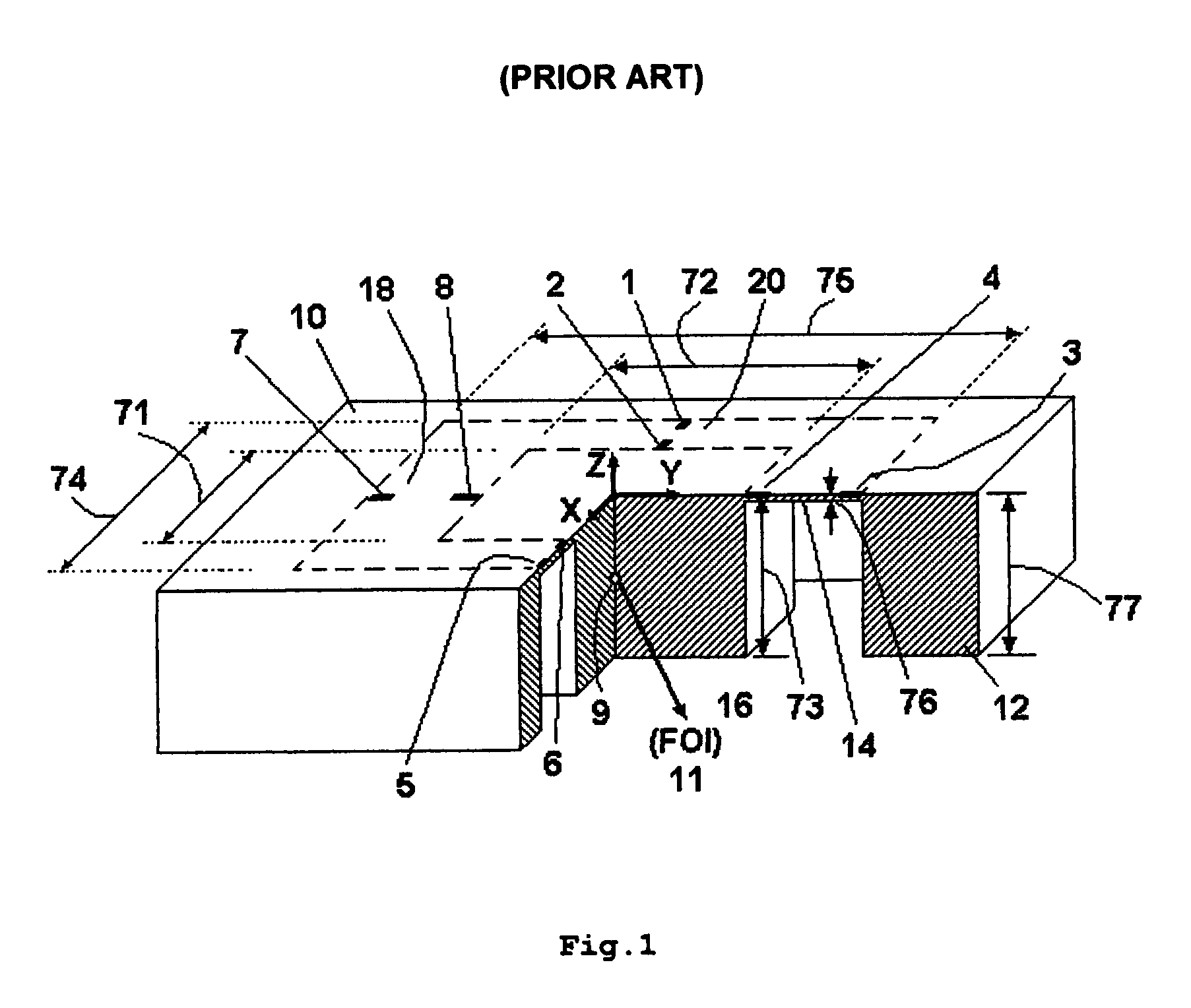
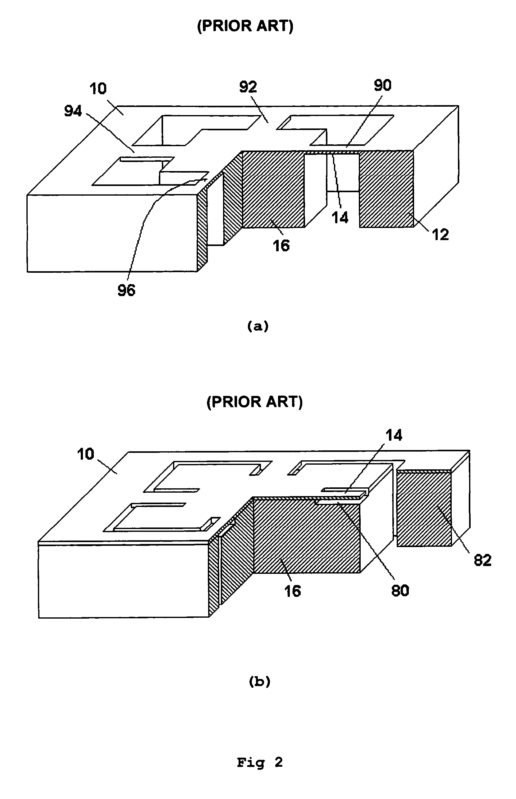
[0126]FIG. 5 shows a structure of a three-axis accelerometer die according to a The die 10 has a frame 12, uniform square diaphragm suspension with sides 18 and 20 of span 14, and a proof mass 16 in the form of a parallelepiped.

[0127] The improvement made to the three-axis accelerometer shown in FIG. 5 is by using a composite proof mass 16 consisting of two parts. The first part is integral with the semiconductor substrate used in fabrication of the sensor die. This part forms an outer portion of the proof mass 16 shown in FIG. 5. The inner portion 30 of the proof mass 16 is made out of a material having average density significantly higher than that of silicon. Using a composite proof mass gives significant increase of sensitivity. Preferably, metals and alloys like W, Au, Cu, Ta, Pb—Sn and others can be used in order to make the central part of the proof mass. For example, if silicon occupies one third and tin-lead alloy with density of 10.0 mg / mm3 occupies two thirds of the volu...

fourth embodiment

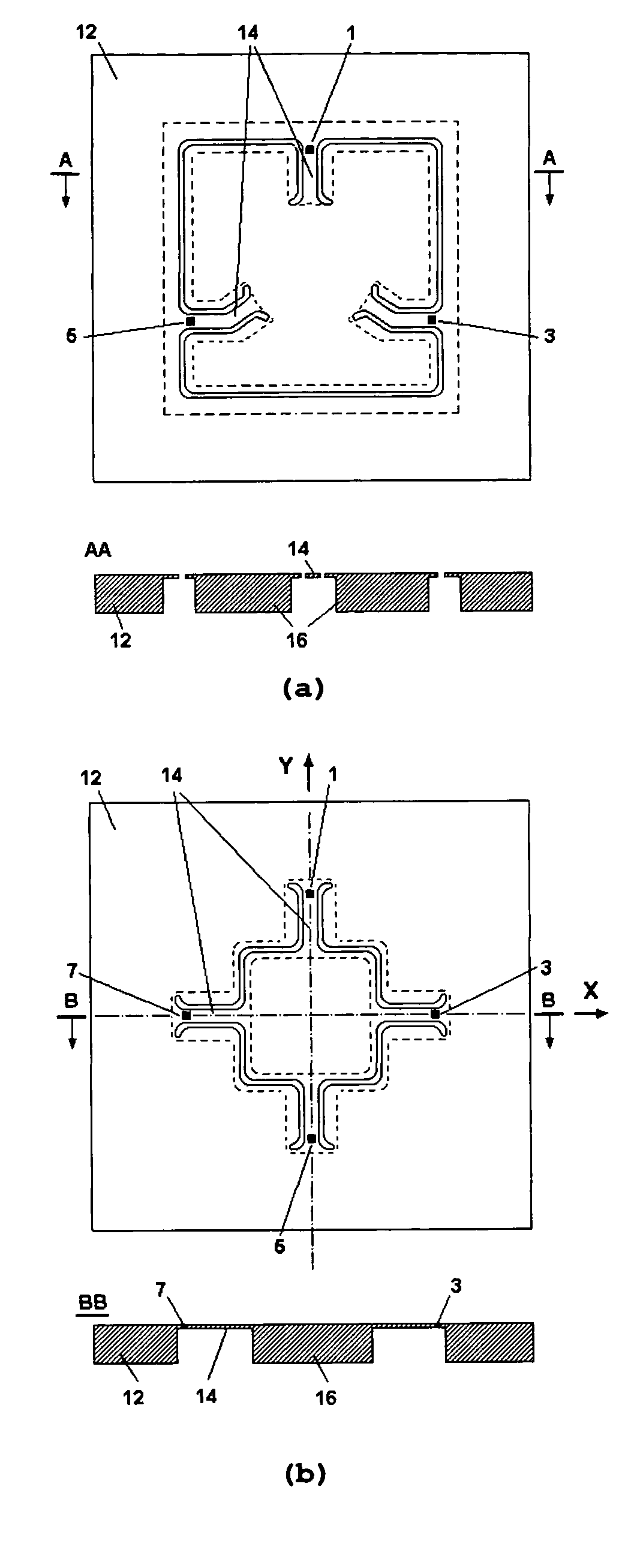
[0134] Another option of increasing sensitivity by decreasing stiffness of the suspension is the partial releasing of the diaphragm connection with the frame according to the One way to do that is to make narrow slots in the diaphragm somewhere between the connection area with the proof mass and the frame. In general, the slots can be curved. Some portions of the slots can be oriented along the radial directions toward the center of the diaphragm. The other portions can be tangential. The resulting suspension has smaller stiffness and supports the same proof mass. Therefore, structure with the slotted diaphragm has higher sensitivity than one with a solid diaphragm suspension.

[0135] Numerous suspension shapes and numerous proof mass shapes can be created by micromachining of the proof mass and making slots in the diaphragm. Some designs are shown in FIGS. 6-8.

[0136]FIG. 6 shows a structure 20 of a three-axis accelerometer. The sensor chip 18 has a frame 12 with a square opening de...

fifth embodiment

[0144] Design of three-axis accelerometer utilizing stress sensors can be improved by using suspensions with stress concentrators according to Stress concentrators localize the desired level of stress only in the specific areas of suspension, where stress sensitive IC components are located. It makes the rest of the suspension is less stressed and more reliable. Therefore, using stress concentrators allows increasing thickness or width of the suspension while keeping the same or somewhat higher sensitivity than without stress concentrators. Thicker suspension allows better control and, therefore, provides better reproducibility and reliability. Wider suspension allows placing larger number of stress sensors in the same area that can be used for reduction of cross-axis sensitivity or increasing sensitivity. Alternatively, the size of the sensor can be decreased.

[0145] An example of a three-axis accelerometer structure with stress concentrators is shown in FIG. 9. Shallow cavities 56...


PUM


Abstract

A system and method for inputting motion measurement data into a computationally based device are provided. In a first version three-axis accelerometer determines components of an inertial force vector with respect to an orthogonal coordinate system. The accelerometer includes a sensor die made of a semiconductor substrate having a frame element, a proof mass element, and an elastic element mechanically coupling the frame and the proof mass. The accelerometer also has three or more stress-sensitive IC components integrated into the elastic element adjacent to the frame element for electrical connectivity without metal conductor traversal of the elastic element.

Description

[0001] This application is a Continuation to Provisional Patent Application No. 60 / 538,638 filed on Jan. 24, 2004, and which is incorporated herein by reference in its entirety and for all purposes. REFERENCES [0002] U.S. patent documents 1. 4,967,605November 1990Okada73 / 5172. 5,182,515January 1993Okada73 / 5173. 5,295,386March 1994Okada73 / 5174. 5,485,749January 1996Nohara73 / 517BACKGROUND OF THE INVENTION [0003] 1. Field of the Invention This invention relates to semiconductor devices, Micro Electro Mechanical Systems (MEMS), sensors and more specifically to three dimensional (3D) three-axis accelerometers, vibration sensors and inclinometers for consumer and other applications. [0004] 2. Description of the Related Art MEMS accelerometers are known for more than 25 years and they are widely used in different areas. Automotive air-bag applications currently represent the biggest MEMS accelerometer market. Furthermore, there are only few known MEMS accelerometers that can measure all t...

Claims


Application Information

Patent Timeline
IPC IPC(8): G01P15/08G01P15/12G01P15/18
CPCG01P15/18G01P15/123G01P2015/084G01P2015/0842
Inventor VAGANOV, VLADIMIRBELOV, NICKOLAI
Owner VAGANOV VLADIMIR
Why Eureka
Try Eureka