Microfluidic treatment method and device

a microfluidic treatment and microfluidic technology, applied in the direction of flow mixers, diaphragms, electrolysis, etc., can solve the problems of affecting the simplification of experimental procedures, affecting the simplification of the experimental procedure, so as to achieve the effect of easy compilation into the database and free control of the concentration gradien

Inactive Publication Date: 2005-07-28
EBARA CORP
View PDF3 Cites 133 Cited by
  • Summary
  • Abstract
  • Description
  • Claims
  • Application Information

AI Technical Summary

Benefits of technology

[0110] According to the DGGE microchip electrophoretic apparatus and electrophoretic method of the present invention, the concentration gradient of a nucleic acid denaturant can be formed accurately, and the concentration gradient can be controlled freely. Particularly, it is possible to provide, in large quantities, analytical chips which can reproduce always the same denaturing gradient or denaturant arrangement. As a result, strict comparisons and studies of different data become possible, producing various advantages, for example, such that in analyzing the structure of a microbial community based on a comparison of nucleic acids (typically, comparison of base sequences of rRNA gene) contained in samples being analyzed, collected data can be easily compiled into database.

Problems solved by technology

The problem of difficulty in mixing is a general problem encountered not only in microchip electrophoresis, but also in mixing a plurality of liquids in a microchannel.
Thus, the liquids mix substantially only upon molecular diffusion at the interface, and this hinders prompt mixing.
The above problem has been a factor for impeding the simplification of the experimental procedure, the shortening of the analysis and reaction times, high throughput, microchip downsizing, and high accuracy (for example, high resolution) in microchip apparatuses as a whole, such as analytical microchips and microreactors.
In this case, however, the mixing microchannel accounts for a large area, thus posing the defects that downsizing of the apparatus is difficult, and that the liquids take time for passing the channel, thus lengthening the analysis time and the reaction time.
This makes it impossible to exercise quantitative concentration control such that a concentration gradient is formed in the flowing direction.

Method used


Image

  • Microfluidic treatment method and device
  • Microfluidic treatment method and device
  • Microfluidic treatment method and device

Examples


embodiment

A Concerning DGGE

[0328] In embodiment A, a denaturing gradient is formed so as to be continuously changed in the direction of electrophoresis.

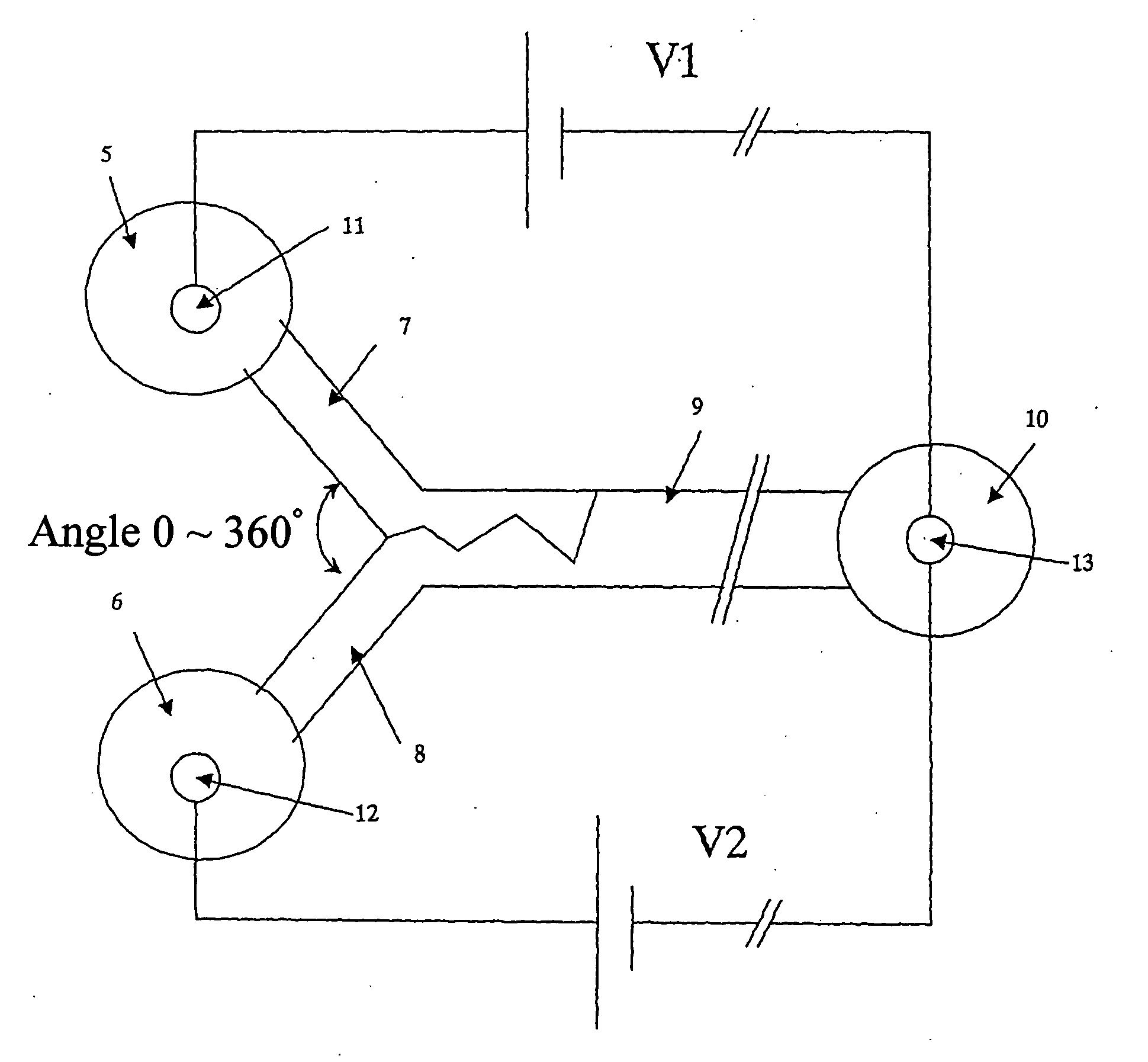
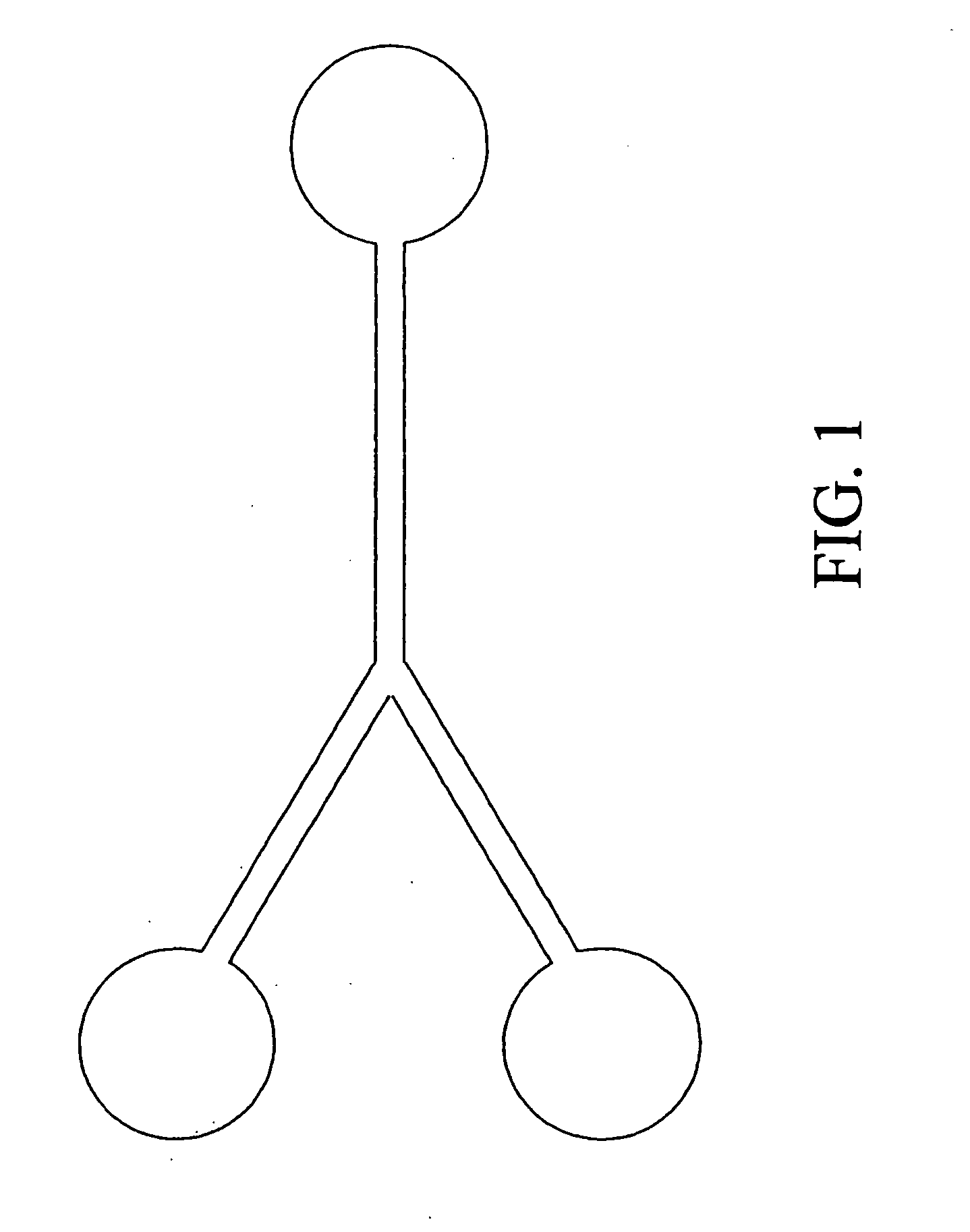
[0329] The microchip electrophoretic apparatus of the present embodiment comprises at least two liquid-introducing microchannels for introducing buffer solutions containing a denaturant at different concentrations; and a mixing microchannel to which the at least two liquid-introducing microchannels connect, and a concentration gradient region of the denaturant is formed by the convergence, in the mixing microchannel, of the buffer solutions introduced at varying ratios from the liquid-introducing microchannels.

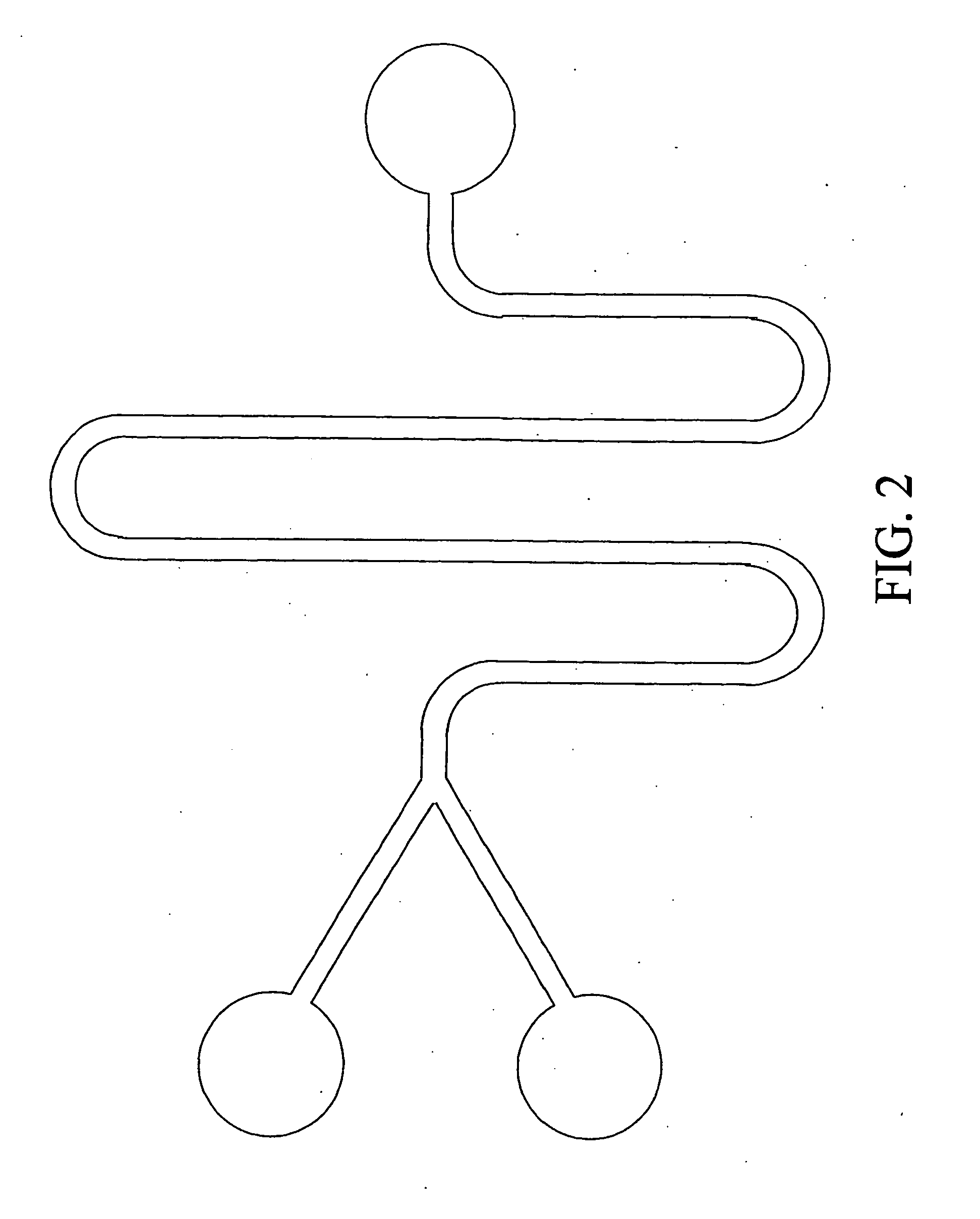
[0330] A preferred embodiment has a mixing enhancing means for enhancing the mixing of the buffer solutions converging in the mixing microchannel. As this mixing enhancing means, each of the aforementioned embodiments 1-1 to 2-3, and any combination of these embodiments can be applied.

Microchip Electrophoretic Apparatus of the Embodi...

embodiment b concerned

with DGGE

[0367] The DGGE method of the embodiment B comprises arranging buffer solution zones (electrophoretic gel) containing a denaturant at different concentrations alternately in the direction of electrophoresis, and introducing an analyte into the resulting gradient region for electrophoresis.

[0368] In the microchip electrophoretic apparatus of the embodiment B, buffer solution zones containing a denaturant at different concentrations are arranged alternately in a microchannel in the direction of electrophoresis, and an analyte is introduced into the resulting gradient region for electrophoresis.

(1) Principle of the Present Embodiment

[0369] A method for separating double-stranded nucleic acids by the embodiment B is characterized by arranging at least two buffer solution zones containing a denaturant at different concentrations alternately in the direction of electrophoresis of the nucleic acids. The nucleic acids are electrophoretically moved in a discontinuous arrangement...

example 1

[0441] Two double-stranded nucleic acids having different base sequences were separated by use of a microchip electrophoretic apparatus as described in each of the aforementioned embodiments. A nucleic acid sample containing a V3 region of 16S rRNA gene obtained from two microorganisms of the genus Sphingomonas was prepared as an analyte.

[0442] In experiments, the two microorganisms were cultured in liquid media, and then collected by centrifugation. The cells were mixed, and nucleic acids were extracted from the mixed cells by using benzyl chloride. The extracted nucleic acids were subjected to PCR using universal primers (forward; 5′-CGCCCGCCGC GCGCGGCGGG CGGGGCGGGG GCACGGGGGG CCTACGGGAG GCAGCAG-3′ (sequence No. 1), reverse; 5′-ATTACCGCGG CTGCTGG-3′ (sequence No. 2)) targeting the V3 region of the 16S rRNA gene. The resulting PCR product was used as a final nucleic acid sample. The universal primers used were FITC-labeled at the 5′-terminal. The forward primer was provided with a...


PUM

PropertyMeasurementUnit
sizeaaaaaaaaaa
sizeaaaaaaaaaa
depthaaaaaaaaaa

Abstract

The present invention relates to a microchip apparatus using liquids. More specifically, the invention provides a liquid mixing apparatus comprising at least two microchannels for introducing liquids and a mixing microchannel that connects to the at least two liquid-introducing microchannels, wherein the liquids are transported from the respective liquid-introducing microchannels toward the mixing microchannel, the apparatus further comprising means for enhancing the mixing of the liquids that converge in the mixing microchannel. The invention also provides an electrophoretic apparatus and a microchip electrophoretic apparatus for denaturing gradient gel electrophoresis.

Description

BACKGROUND OF THE INVENTION [0001] This invention relates to a microfluid apparatus, and a miniaturized chemical analysis apparatus. More particularly, the present invention relates to a liquid mixing apparatus and a liquid mixing method for causing small amounts of two or more liquids (may be referred to hereinafter as “reagent solutions”) to converge in a microchannel, thereby mixing the liquids with high efficiency. The present invention relates, particularly, to a microreactor, etc. for producing, for example, a desired reaction product with high efficiency by a chemical reaction between the liquids mixed in the microchannel. [0002] Further, the present invention relates to a chemical analysis system for separating and analyzing an analyte by utilizing the concentration gradient of a denaturant for the analyte. More particularly, the present invention relates to denaturing gradient gel electrophoresis (DGGE) for separating double-stranded nucleic acids (may hereinafter be referr...

Claims


Application Information

Patent Timeline
Patent Type & Authority Applications(United States)
IPC IPC(8): B01F5/06B01F7/00B01F11/00B01F11/02B01F13/00B01J19/00B01L3/00G01N27/447
CPCB01F5/061G01N27/44791B01F5/0647B01F5/0654B01F7/00291B01F11/0071B01F11/0266B01F13/0059B01F2005/0621B01J19/0093B01J2219/00783B01J2219/00889B01J2219/00891B01L3/50273B01L3/502738B01L3/502746B01L2300/0816B01L2300/0867B01L2400/0421B01L2400/082G01N27/44704B01F5/0646B01F25/4317B01F25/431B01F25/4337B01F25/4331B01F25/433B01F27/1125B01F31/65B01F31/86B01F33/30B01J19/00B01F23/40B01F25/00B01F25/40B01F25/431971
Inventor MORITA, TOMOYUKIMIYA, AKIKOFUKUDA, AKIRANOMI, MOTOHIKOICHIKI, KATSUNORITSUJIMURA, MANABUSHIMIZU, SHUNSUKE
Owner EBARA CORP
Why Eureka
Try Eureka