Optical compensation film and liquid crystal display
- Summary
- Abstract
- Description
- Claims
- Application Information
AI Technical Summary
Benefits of technology
Problems solved by technology
Method used
Image

Examples
example 1
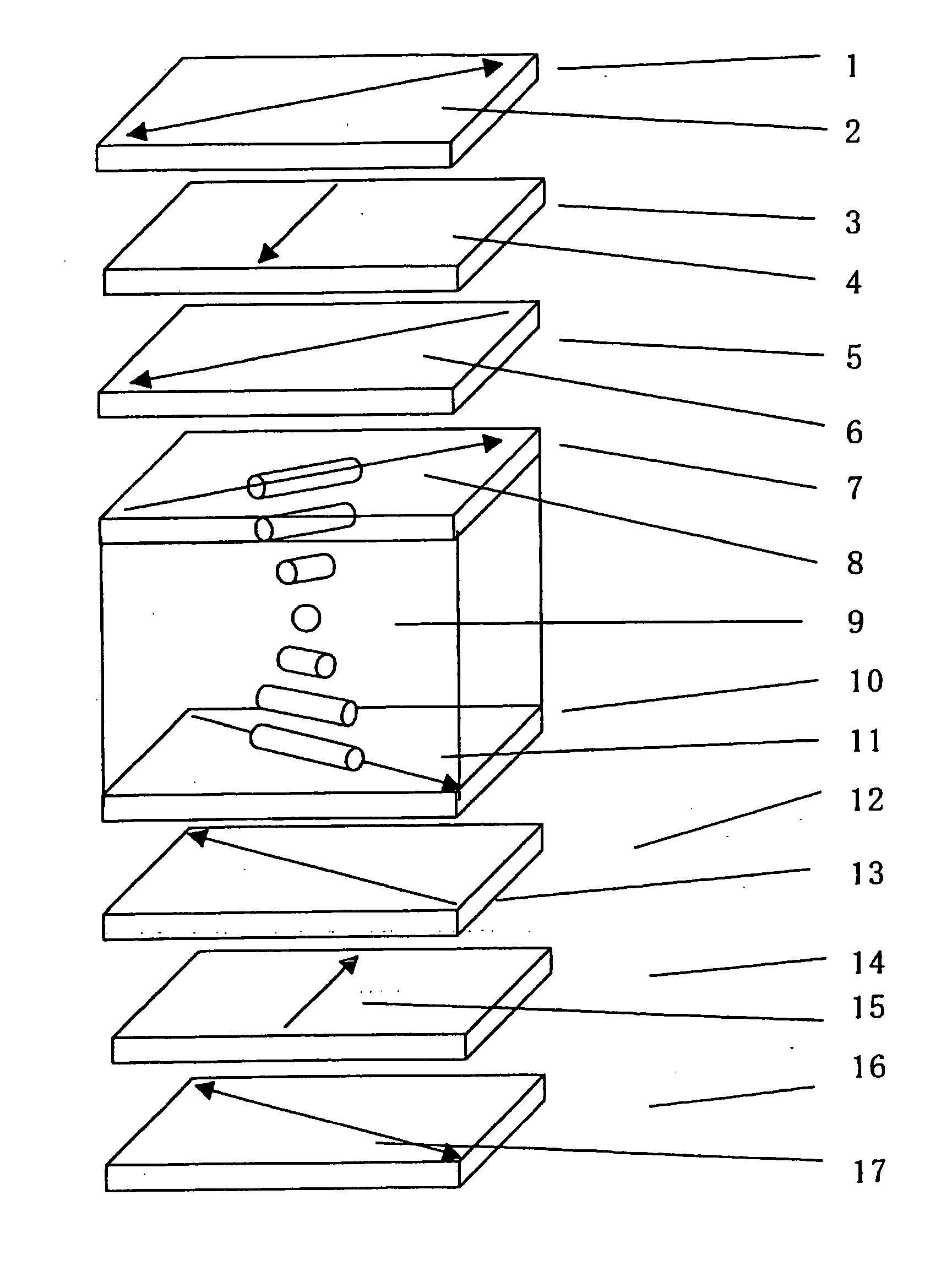
[0193] A liquid crystal display having the configuration shown in FIG. 1 was prepared. In some detail, an upper polarizing plate 1, an upper second optical anisotropic layer 3, an upper first optical anisotropic layer 5, a liquid crystal cell (an upper substrate 7, a liquid crystal layer 9, a lower substrate 10), a lower first optical anisotropic layer 12, a lower second optical anisotropic layer 14 and a lower polarizing plate 16 were stacked in this order as viewed in the observation direction (from above). A backlight comprising a cold cathode fluorescent lamp (not shown) was provided under the lower polarizing plate.
[0194] The members used and the method for the preparation thereof will be described hereinafter.
[0195] A liquid crystal cell having a gap (d) of 4 μm was prepared by dropwise injecting a liquid crystal material having a positive dielectric constant anisotropy into the gap between the substrates to form a liquid crystal layer 9 having Δnd of 350 nm (Δn is the refra...
example 2
[0213] A liquid crystal display was prepared in the same manner as in Example 1 except that lamination was made such that the rubbing direction of both the first and second optical anisotropic layers are arranged in the direction of 45° with respect to the in-plane slow axis of the cellulose acetate film (parallel to casting direction) and the rubbing direction of both the upper and lower substrates of TN mode liquid crystal cell are arranged in the direction of 45° with respect to the in-plane slow axis of the cellulose acetate film (parallel to casting direction).
[0214] A 60 Hz rectangular voltage was applied to the liquid crystal display thus prepared. The liquid crystal display thus prepared operated in normally white mode that performs white display at 1.5 V and black display at 3 V. The liquid crystal display was then evaluated for optical properties in the same manner as in Example 1. The results are set forth in Table 1.
example 3
[0215] An alignment layer was formed on the cellulose acetate film in the same manner as in Example 1. The alignment layer was then subjected to rubbing in the direction of 25° with respect to the slow axis of the cellulose acetate film. A coating solution obtained in the same manner as in the formulation of the coating solution for the second optical anisotropic layer of Example 1 except that the amount of methyl ethyl ketone was 207 g and 7.5 g of the following chiral agent was added was spread over the alignment layer in the same manner as in Example 1 to form an optical anisotropic layer.
Chiral Agent
[0216] In the optical anisotropic layer thus prepared, the discotic liquid crystalline compound was observed to have an arrangement such that the angle (tilt angle) between the surface of the disc and the transparent protective film increases from the transparent protective film toward the interface with air (hybrid alignment). Thus, the discotic liquid crystalline compound was o...
PUM
 Abstract
Description
Claims
Application Information
 - Generate Ideas
- Intellectual Property
- Life Sciences
- Materials
- Tech Scout
- Unparalleled Data Quality
- Higher Quality Content
- 60% Fewer Hallucinations
Browse by: Latest US Patents, China's latest patents, Technical Efficacy Thesaurus, Application Domain, Technology Topic, Popular Technical Reports.
© 2025 PatSnap. All rights reserved.Legal|Privacy policy|Modern Slavery Act Transparency Statement|Sitemap|About US| Contact US: help@patsnap.com