
Solid state diamond Raman laser

a laser and solid-state technology, applied in the field oframan lasers, can solve the problems of thermal limitation of solid-state raman lasers, and achieve the effect of high-power applications

Inactive Publication Date: 2005-07-28
SPECTRA SYST CORP
View PDF12 Cites 48 Cited by
  • Summary
  • Abstract
  • Description
  • Claims
  • Application Information

AI Technical Summary

Benefits of technology

[0006] An advantage of the present invention is that the solid state Raman laser is capable of operating in high power applications.

Problems solved by technology

A variety of crystalline materials have been used in solid state Raman lasers, however solid state Raman lasers typically become thermally limited due to increased Raman linewidth with increasing temperature.

Method used


Image

  • Solid state diamond Raman laser
  • Solid state diamond Raman laser
  • Solid state diamond Raman laser

Examples


example

[0028] A Raman laser was produced with a single crystal diamond Raman material. An Nd:YAG laser was used, frequency doubled to 532 nm operating at 40 Hz, 1.62 ml, 3 nsec per pulse with approximately a 0.7 mm spot size. The single crystal diamond sample measured approximately 5 mm×5 mm and approximately 0.5 mm thick. The faces of the sample were polished with the edges remaining unpolished.

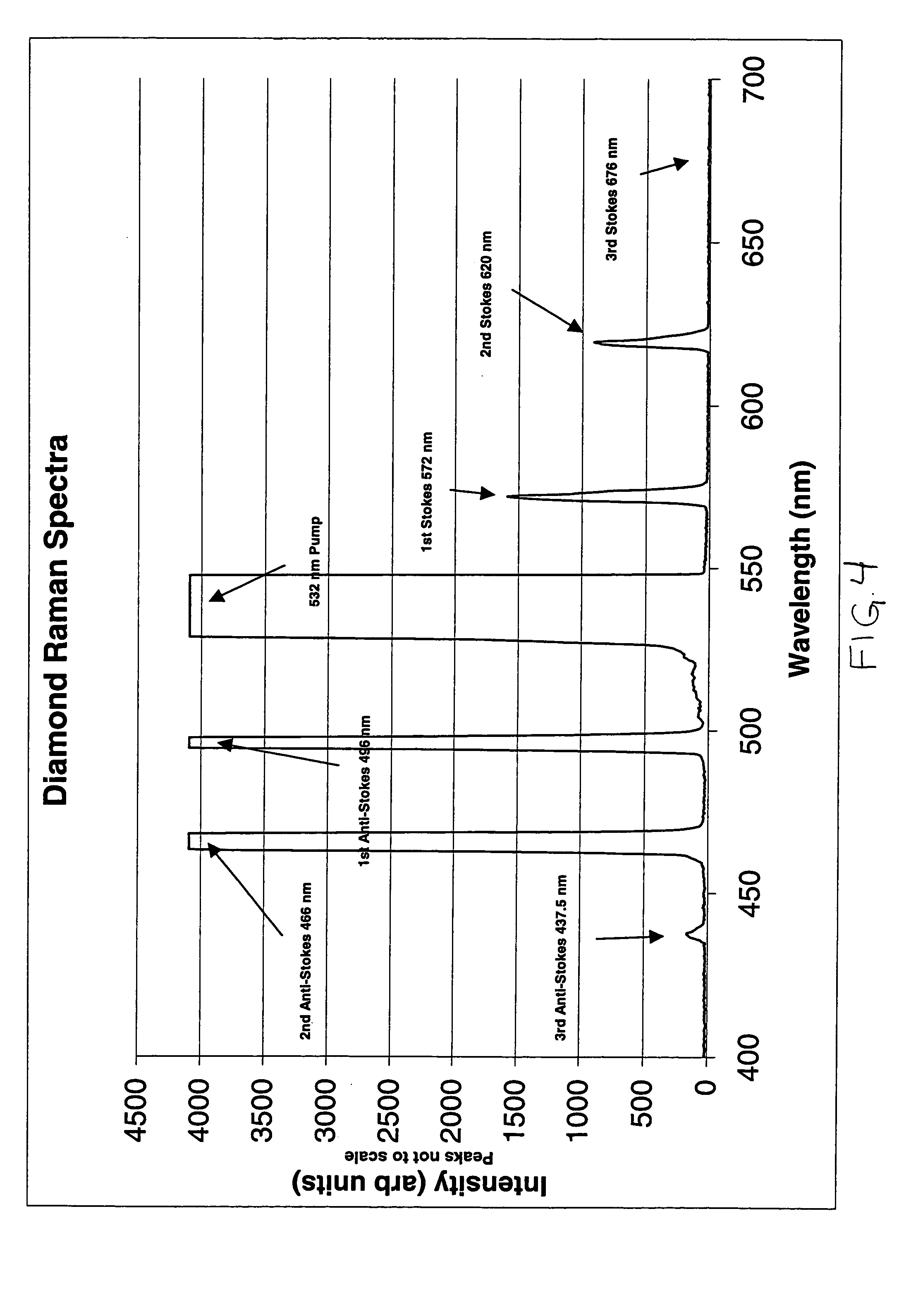
[0029] A Raman spectra of the single crystal diamond sample was collected and is shown in FIG. 4. FIG. 5 shows the schematic arrangement of the Raman spectra collection system used to obtain the Raman spectra shown in FIG. 4.

[0030] The diamond sample was positioned in the optical path of the Nd:YAG laser without any additional optical elements employed and a Raman beam was generated with a single pass of the Nd:YAG laser.

[0031] For a Raman laser the threshold condition is given by:

Threshold=1=R1R2e2(golI-L)

[0032] Where R1 is the reflection coefficient of mirror 1, R2 is the reflection coeffici...


PUM


Abstract

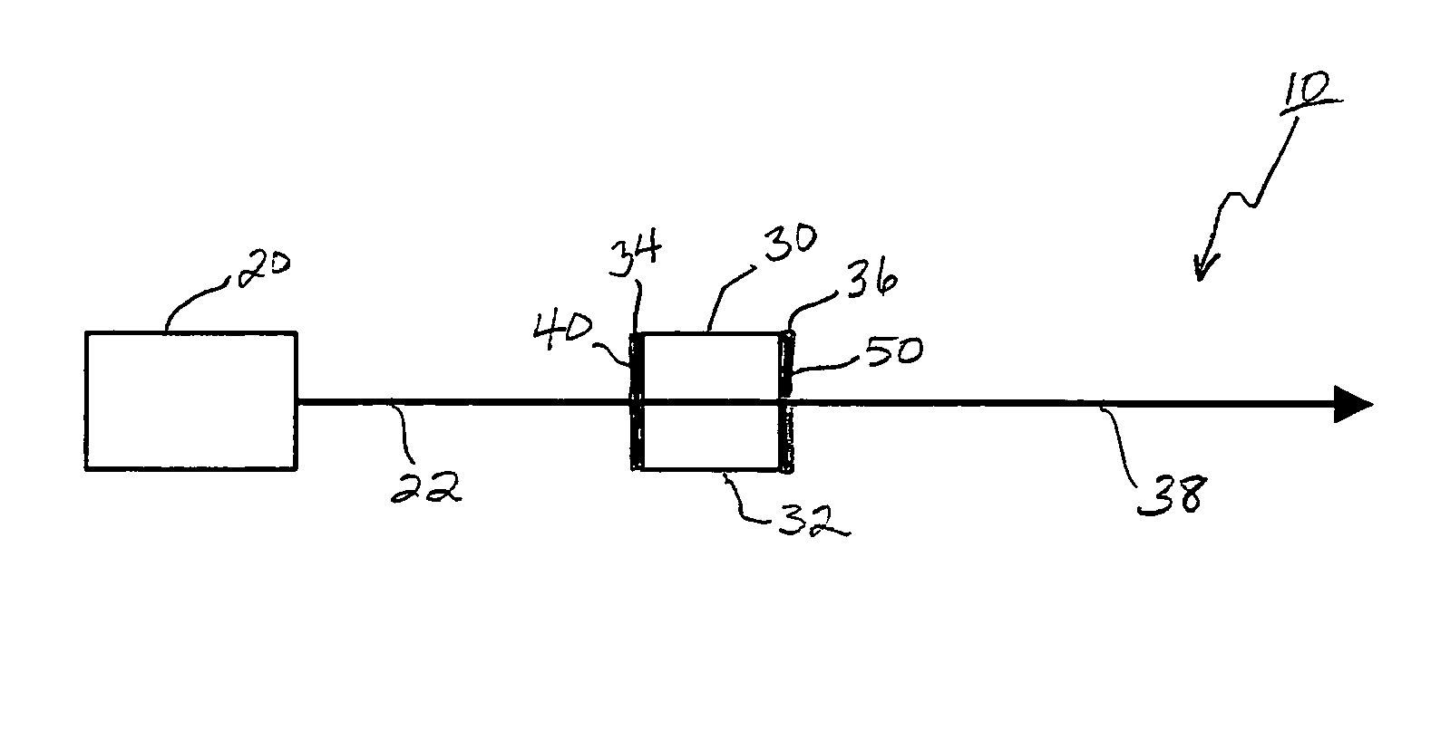
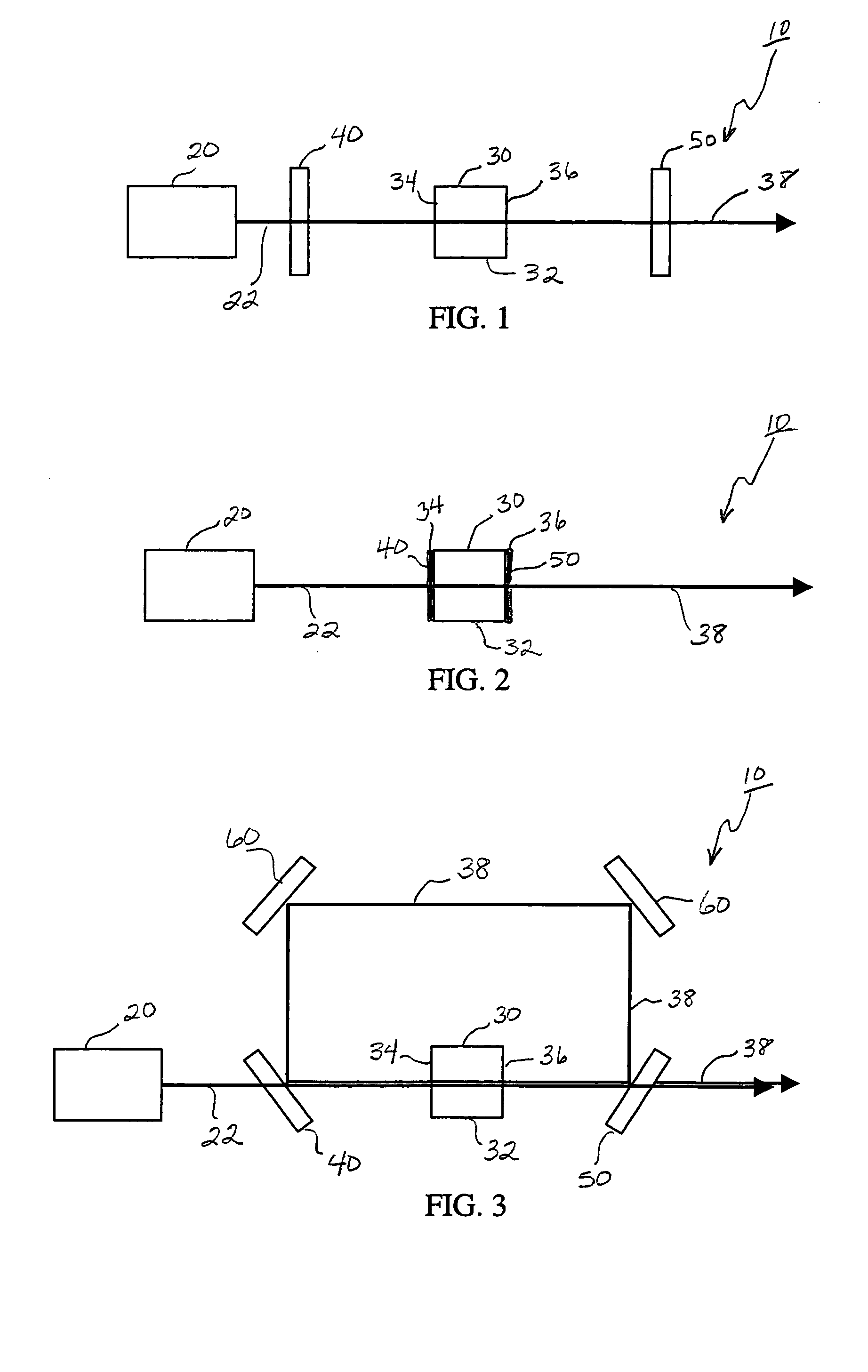
A solid state Raman laser includes a laser pump for producing a first radiation at a high power and at a first wavelength along an optical path, a solid Raman active medium in the optical path of the first radiation, the medium including single crystal diamond having a first surface and a second surface, where the first radiation at a high power produces stimulated Raman scattering in the medium and the medium generates a second radiation at a second wavelength, a first optical element in the optical path of the first radiation, wherein the first optical element allows the first wavelength to be transmitted and allows the second wavelength to be reflected, and a second optical element in the optical path of the first radiation, wherein the second optical element allows the first wavelength to be transmitted and allows the second wavelength to be reflected.

Description

CROSS-REFERENCE TO RELATED APPLICATIONS [0001] This application claims the benefit under 35 U.S.C. § 119(e) to U.S. Provisional Application No. 60 / 513,492 filed Oct. 22, 2003, entitled “NONLINEAR OPTICS IN BULK DIAMONDS AND ITS APPLICATIONS,” the disclosure of which is incorporated by reference herein.FIELD OF THE INVENTION [0002] This invention relates to Raman lasers and, in particular, to a diamond material suitable for use in solid state Raman lasers capable of high power operation. BACKGROUND OF THE INVENTION [0003] Raman scattering is an inelastic light scattering process where the scattered radiation has a lower energy from the incident radiation. Stimulated Raman scattering (SRS) takes place with intense electromagnetic fields enhancing the process, where light at one wavelength, the pump wavelength, is converted to another wavelength, the Stokes wavelength, accompanied by an excitation within a Raman medium. The Raman medium used in Raman lasers includes solids, liquids and...

Claims


Application Information

Patent Timeline
Patent Type & Authority Applications(United States)
IPC IPC(8): H01S3/06H01S3/083H01S3/094H01S3/16H01S3/30
CPCH01S3/0604H01S3/0627H01S3/083H01S3/30H01S3/094076H01S3/16H01S3/163H01S3/094
Inventor LAWANDY, NABIL M.AFZAL, ROBERT S.
Owner SPECTRA SYST CORP
Learn More