Variable blower controller for vehicle

a variable speed, blower controller technology, applied in the direction of motor/generator/converter stopper, dynamo-electric converter control, instruments, etc., can solve the problems of new noise problem of blower controller, power requirements in the mid-blower speed, and large heat sinks, so as to achieve greater control of output voltage and more robust motor protection strategies

Inactive Publication Date: 2005-07-28
DONNELLY CORP
View PDF12 Cites 9 Cited by
  • Summary
  • Abstract
  • Description
  • Claims
  • Application Information

AI Technical Summary

Benefits of technology

[0006] The present invention is intended to provide an improved microprocessor-based variable blower controller for use in a vehicle including smart power management or intelligent power management. The variable blower controller employs the functionality of an on-board microprocessor to achieve greater control of output voltage, more robust motor protection strategies, and wider-applicability for extreme vehicle conditions.
[0010] The variable blower controller with smart or intelligent power management uses a field effect transistor (FET) design, and includes a microprocessor, which receives feedback on motor current, battery voltage, and / or device temperature. The microprocessor may adjust an output in response to the feedback. Therefore, the variable blower controller of the present invention has the ability to give a number of additional functions / benefits, such as smart power management, tighter output performance, flexible output performance, dynamic current limiting / enhanced motor protection, and / or the like.

Problems solved by technology

These devices were more adjustable than the resistor cards, but the requirement to dissipate the required power in linear mode mandated the use of large, heavy, and costly heat sinks.
This is possible due to the low drain-source resistances available in the FET devices.
However, the power requirements in the mid-blower speeds continue to require a large heat sink to dissipate the power.
However, the switching of the controller has introduced a new problem of noise for the blower controller.

Method used


Image

  • Variable blower controller for vehicle
  • Variable blower controller for vehicle

Examples


Embodiment Construction

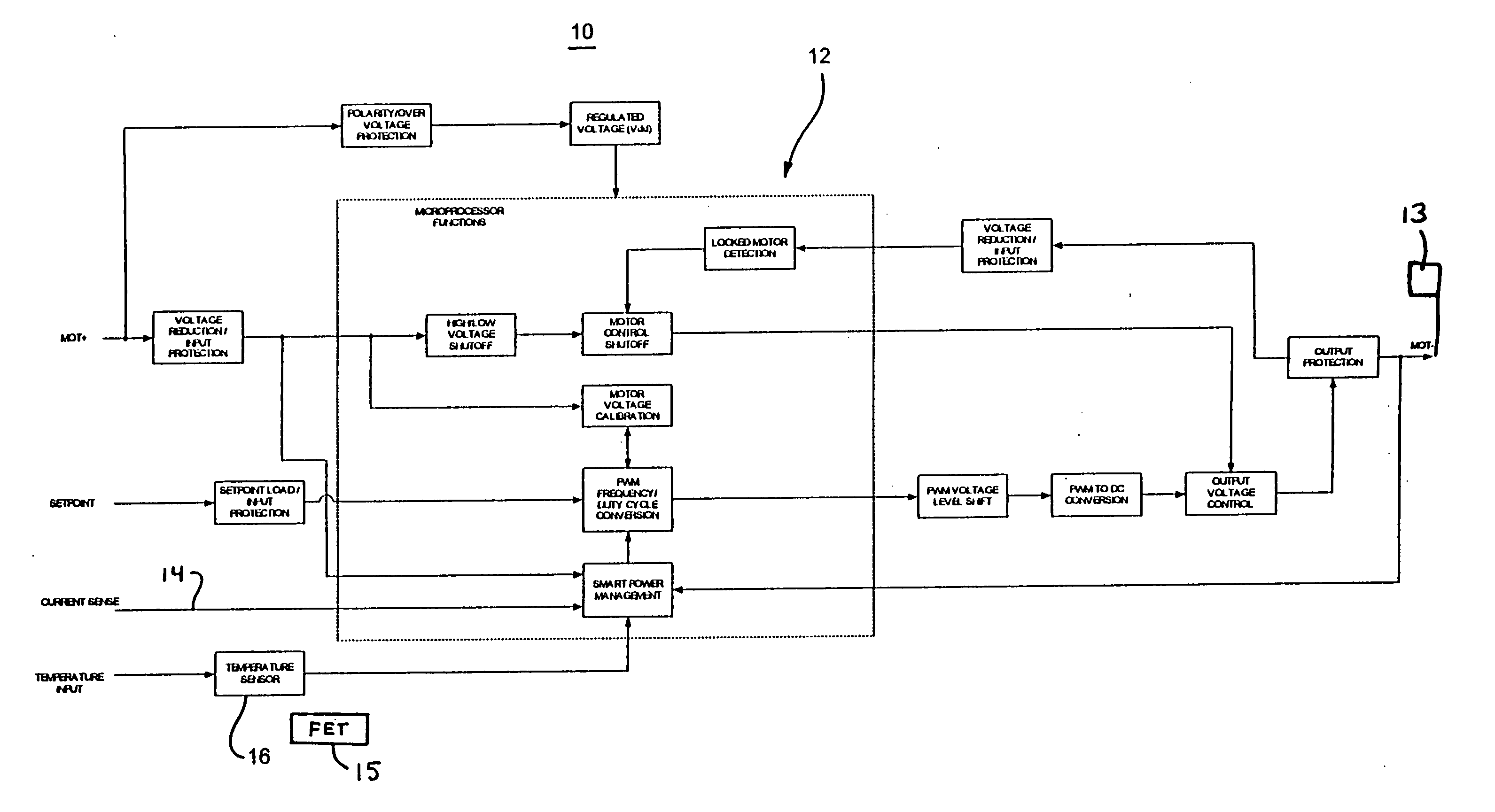
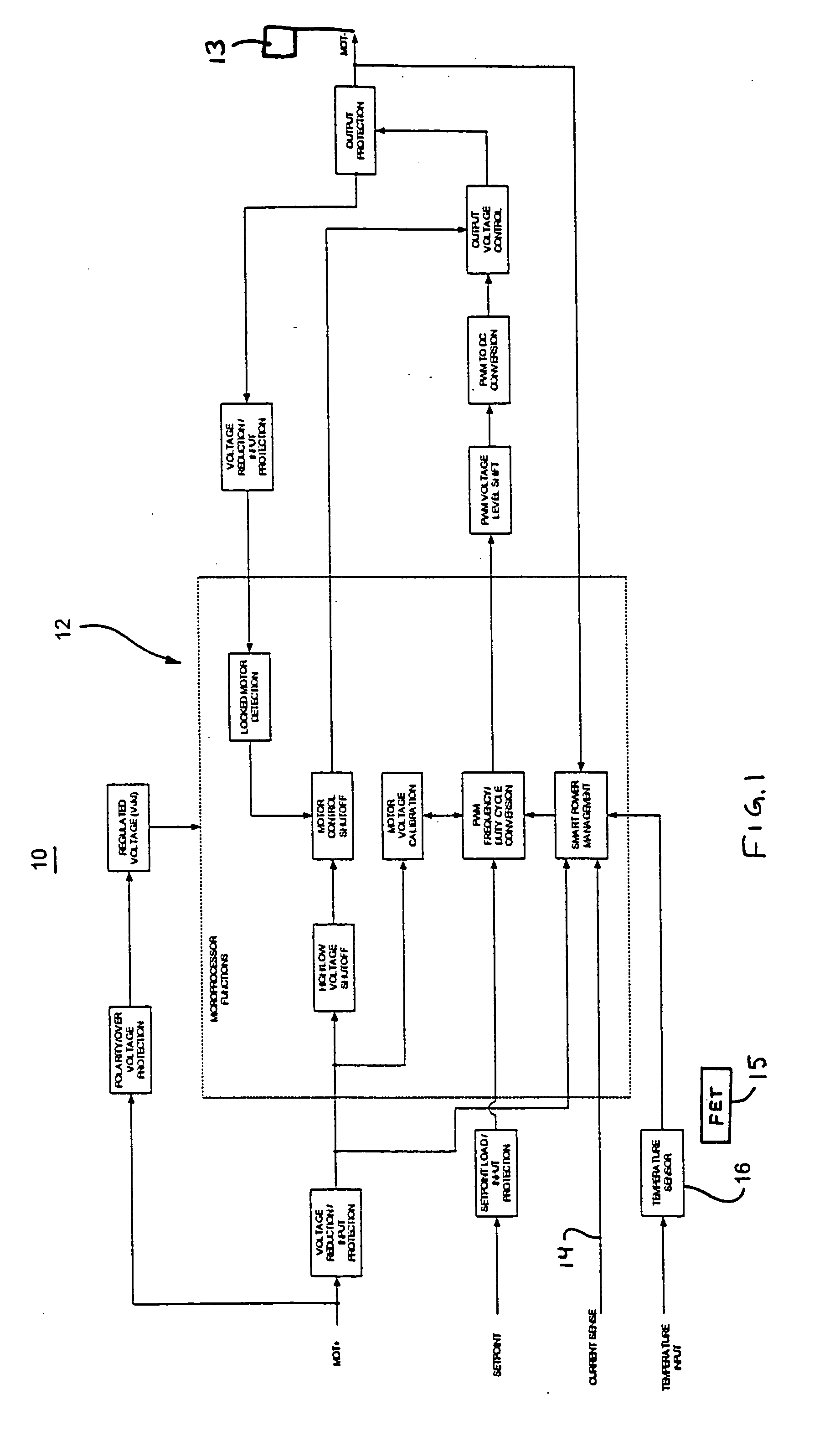
[0013] Referring now to the drawing and the illustrative embodiments depicted therein, a variable blower controller 10 for controlling the blower speed of a heating, ventilation and / or air conditioning system or climate control system of a vehicle includes a microprocessor 12 which is operable to variably control the blower speed of a blower motor 13 of the heating, ventilation and / or air conditioning system or climate control system of the vehicle (FIG. 1).

[0014] The variable blower controller of the present invention provides for smart power management or intelligent power management of the blower. Smart or intelligent power management refers to the controller making an intelligent decision to avoid high-power dissipative modes when system temperatures are above “safe” levels. The smart power management objective is met by keeping a field effect transistor (FET) 15 junction temperature away from design limits or threshold levels where possible. The microprocessor utilizes softwar...


PUM


Abstract

A control system for controlling the climate of a vehicle includes a control element, a temperature sensor, a motor and a microprocessor. The microprocessor may receive a temperature signal indicative of the temperature at the control element and may receive at least one further input. The at least one further input may comprise an input signal indicative of a high side voltage of the motor, a low side voltage of the motor, and / or an electrical current applied to the motor. The control system controls the motor via an output of the microprocessor. The control system may control the motor in response to the temperature signal and the at least one further input. The control system may reduce occurrence of high-power dissipative modes in response to a detection of a temperature above a threshold level via intelligent power management.

Description

CROSS REFERENCE TO RELATED APPLICATION [0001] The present application claims priority of U.S. provisional application, Ser. No. 60 / 377,560, filed May 3, 2002 (Attorney Docket DON01 P-981), which is hereby incorporated herein by reference in its entirety.FIELD OF THE INVENTION [0002] The present invention is related to a blower controller for a blower motor for use in vehicle applications and, more particularly, to a blower controller having a field effect transistor. BACKGROUND OF THE INVENTION [0003] Early vehicle climate control systems utilized resistor cards to provide discrete blower speeds for manual adjustment. These resistor cards introduced different resistances in line with the blower motor to set motor current. To cool the resistor card, the part was typically placed in the air stream of the blower system. [0004] Innovation led to the use of “linear” devices based on circuits using a power bipolar junction transistor (BJT) in combination with a relay to achieve high blowe...

Claims


Application Information

Patent Timeline
Patent Type & Authority Applications(United States)
IPC IPC(8): B60H1/00
CPCB60H1/00828
Inventor GORMAN, BRIAN A.BARNES, SACHA E.WICHLACZ, JOHN T.
Owner DONNELLY CORP
Why Eureka
Try Eureka