Exhaust emission control system for internal combustion engine and exhaust emission control method

a technology of exhaust emission control and internal combustion engine, which is applied in the direction of exhaust treatment electric control, electrical control, separation process, etc., can solve the problems of reducing the output of the internal combustion engine, reducing the time interval, and deteriorating fuel efficiency, so as to avoid excessive filter temperature increase, prevent deterioration of fuel efficiency, and reduce the time interval for the filter recovery process.

Inactive Publication Date: 2005-08-04
TOYOTA JIDOSHA KK
View PDF5 Cites 40 Cited by
  • Summary
  • Abstract
  • Description
  • Claims
  • Application Information

AI Technical Summary

Benefits of technology

[0023] As mentioned above, in the exhaust emission control system for the internal combustion engine and the exhaust emission control method according to the invention, the filter recovery process is performed while avoiding excessiv

Problems solved by technology

As more and more PM is trapped by the filter, the filter tends to have clogging, and accordingly the exhaust resistance increases, thus reducing outputs of the internal combustion engine.
This may reduce the time interval for performing the filter recovery proc

Method used


Image

  • Exhaust emission control system for internal combustion engine and exhaust emission control method
  • Exhaust emission control system for internal combustion engine and exhaust emission control method
  • Exhaust emission control system for internal combustion engine and exhaust emission control method

Examples


first embodiment

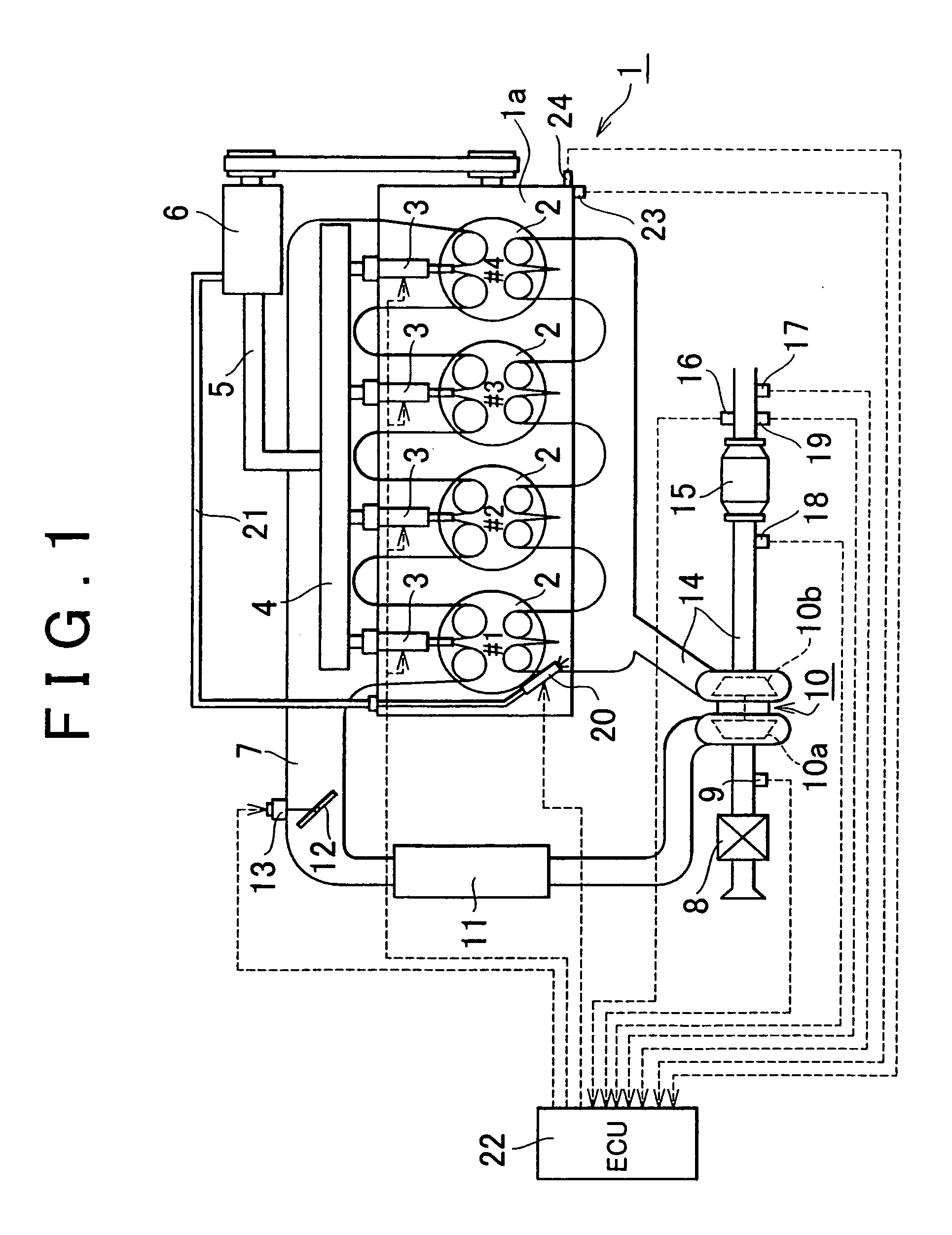
[0029]FIG. 1 is a view that schematically shows the structure of an internal combustion engine that employs an exhaust emission control system according to the embodiment of the invention, and the structure of an intake / exhaust system therein.

[0030] Referring to FIG. 1, an internal combustion engine 1 is a 4-cycle diesel engine of water-cooling type including four cylinders 2, which is provided with fuel injection valves 3 through which fuel is directly injected into each combustion chamber of the cylinders 2, respectively. The respective fuel injection valves 3 are connected to an accumulator (common rail) 4 communicated with a fuel pump 6 via a fuel supply pipe 5.

[0031] The internal combustion engine 1 is connected to an intake passage 7 to which an air cleaner box 8 is connected. The intake passage 7 is provided with an air flow meter 9 at a position downstream of the air cleaner box 8 for outputting an electric signal corresponding to the mass of intake air that circulates wit...


PUM

PropertyMeasurementUnit
Temperatureaaaaaaaaaa
Timeaaaaaaaaaa

Abstract

An exhaust system emission control system for an internal combustion engine includes a filter that traps particulate matters and ass and a controller that starts a filter recovery process by controlling a temperature of the filter to a target temperature to bring an inside of the filter into an oxidizing atmosphere such that the particulate matter trapped and accumulated on the filter is removed through oxidization when an estimated amount of the particulate matters trapped and accumulated on the filter exceeds a predetermined amount. The target temperature is set based on the estimated amount of the ash trapped and accumulated on the filter. Even if the amount of the accumulated particulate matter per unit volume is increased owing to accumulation of the ash on the filter, and oxidization reaction speed of the particulate matter may be reduced, thus preventing excessive temperature increase in the filter.

Description

INCORPORATION BY REFERENCE [0001] The disclosure of Japanese Patent Application No. 2004-025811 filed on Feb. 2, 2004, including the specification, drawings and abstract are incorporated herein by reference in its entirety. BACKGROUND OF THE INVENTION [0002] 1. Field of Invention [0003] The invention relates to a recovery process applied to a particulate filter that purifies exhaust gas discharged from an internal combustion engine, for example, a diesel engine and the like. [0004] 2. Description of Related Art [0005] The process for reducing particulate matters (hereinafter referred to as PM), for example, soot and the like discharged from a vehicle driven by an internal combustion engine into atmosphere has been increasingly desired. There has been introduced a well known particulate filter (hereinafter simply referred to as a filter) that traps the PM discharged from the internal combustion engine disposed in an exhaust passage of the internal combustion engine in response to the...

Claims


Application Information

Patent Timeline
IPC IPC(8): F02D45/00B01D46/42F01N3/02F01N3/023F01N3/025F01N3/035F01N3/08F01N3/36F01N9/00F02B29/04F02B37/00F02D41/02F02M63/02
CPCF01N3/0253Y02T10/47F01N3/0814F01N3/0821F01N3/36F01N9/002F01N9/005F01N2430/08F01N2430/085F01N2560/08F02B29/04F02B37/00F02D41/025F02D41/029F02D2200/0802F02D2200/0812F02M63/0225Y02T10/26F01N3/035Y02T10/12Y02T10/40
Inventor GOTOU, ISAMU
Owner TOYOTA JIDOSHA KK
Why Eureka
Try Eureka