Electrophoresis apparatus and method

a technology of electrophoresis and apparatus, applied in electrodialysis, refrigeration components, diaphragms, etc., can solve the problems of time-consuming and laborious separation of iefs, and achieve the effects of reducing the cost of operation, increasing separation speed, and scaling up capabilities

Inactive Publication Date: 2005-08-04
GRADIPORE +1
View PDF65 Cites 3 Cited by
  • Summary
  • Abstract
  • Description
  • Claims
  • Application Information

AI Technical Summary

Benefits of technology

[0063] An advantage of the present invention is that the apparatus and method have scale-up capabilities, increased separation speed, lower cost of operation, lower power requirements, and increased ease of use.
[0064] Yet another advantage of the present invention is that the apparatus and method have improved yields of the separated component, and improved purity of the separated component.
[0065] These and other advantages will be apparent to one skilled in the art upon reading and understanding the specification.
[0066] Throughout this specification, unless the context requires otherwise, the word “comprise”, or variations such as “comprises” or “comprising”, will be understood to imply the inclusion of a stated element, integer or step, or group of elements, integers or steps, but not the exclusion of any other element, integer or step, or group of elements, integers or steps.
[0067] Any discussion of documents, acts, materials, devices, articles or the like which has been included in the present specification is solely for the purpose of providing a context for the present invention. It is not to be taken as an admission that any or all of these matters form part of the prior art base or were common general knowledge in the field relevant to the present invention as it existed in Australia before the priority date of each claim of this application.

Problems solved by technology

IEF separations often take considerable time because the electrophoretic mobility of each ampholytic species becomes low as they approach the point in the pH gradient where they become isoelectric.

Method used


Image

  • Electrophoresis apparatus and method
  • Electrophoresis apparatus and method
  • Electrophoresis apparatus and method

Examples


example 1

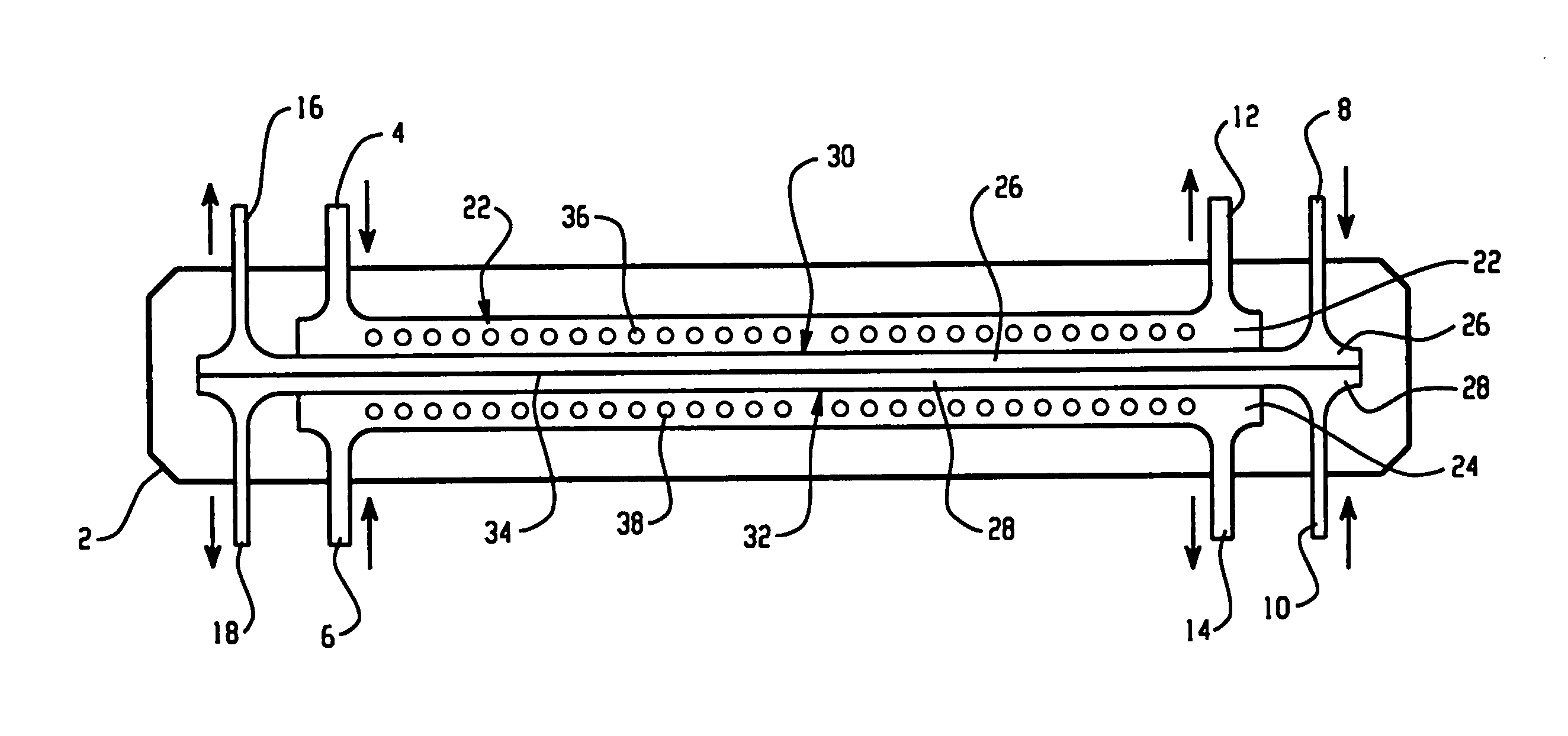
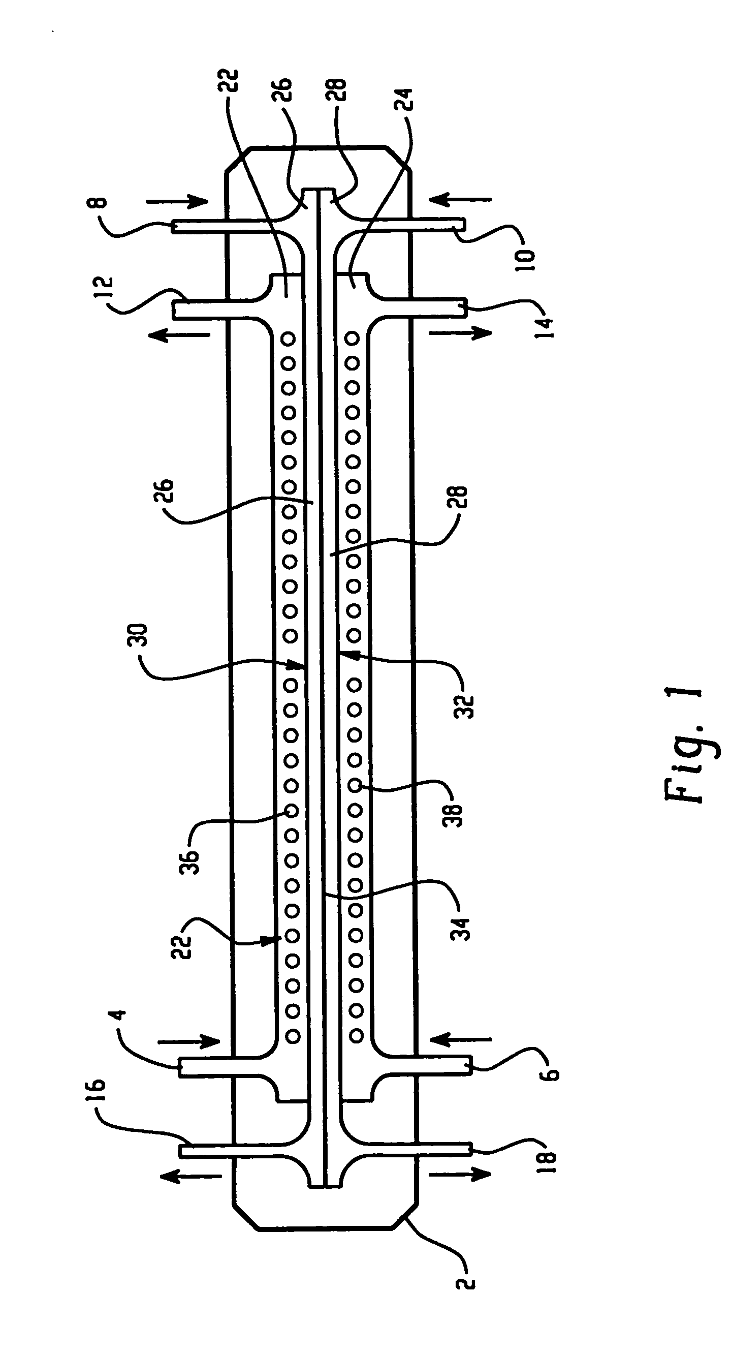
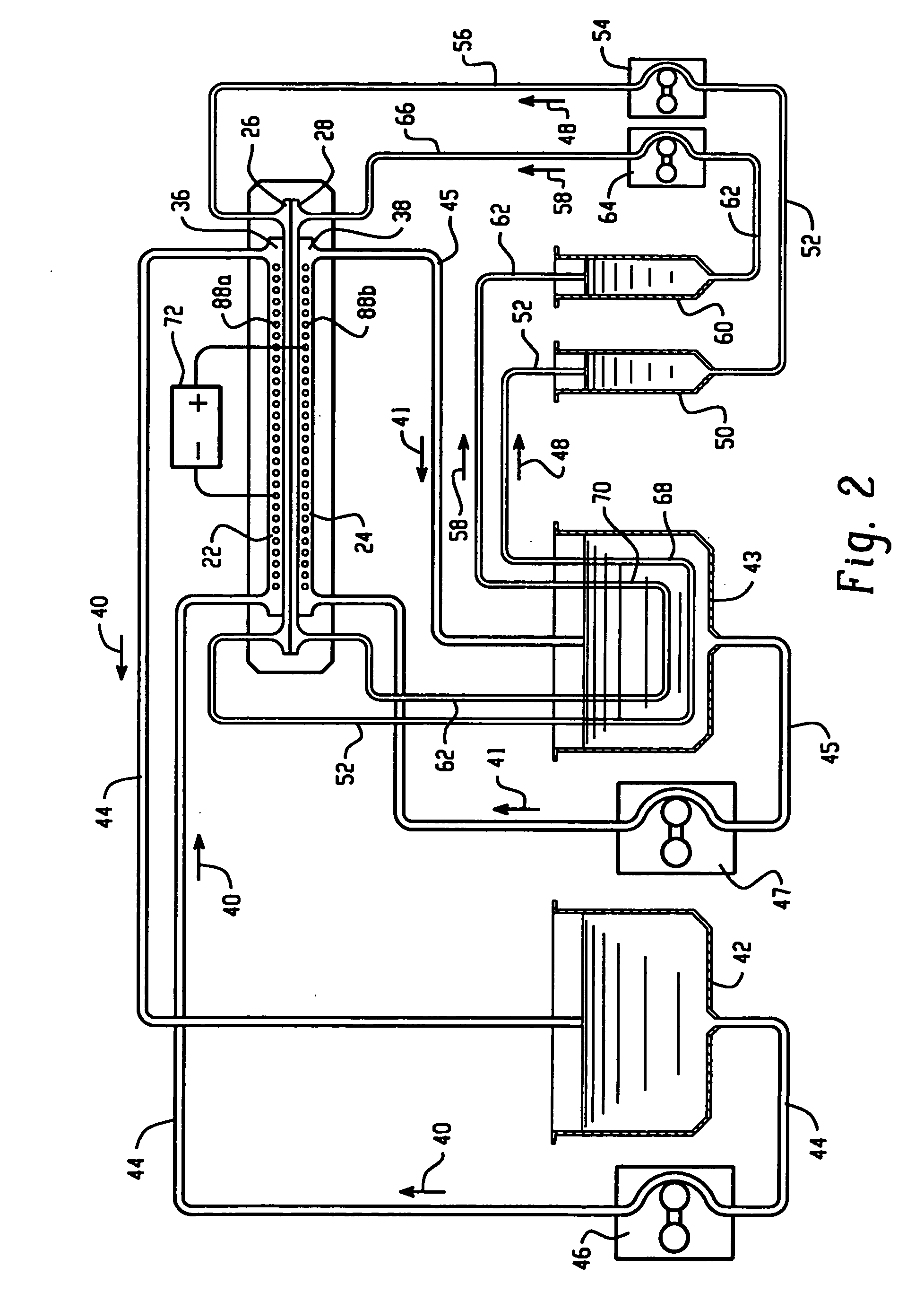
[0128] An apparatus according to the present invention, shown in FIG. 9, was used to separate the proteins present in chicken egg-white into two fractions. An electrophoresis separation cartridge, shown in FIGS. 3 to 7, was adapted to be used in the apparatus. The first ion-permeable barrier placed between the first electrolyte chamber and the first sample chamber was a pI=4.0 isoelectric membrane prepared from Immobiline chemicals (Pharmacia, Sweden), acrylamide and N-N′-methylene bis-acrylamide. The second ion-permeable barrier placed between the first sample chamber and the second sample chamber was a pI=5.0 isoelectric membrane prepared from Immobiline chemicals (Pharmacia, Sweden), acrylamide and N-N′-methylene bis-acrylamide. The third ion-permeable barrier placed between the second sample chamber and the second electrolyte chamber was a pI=7.0 isoelectric membrane prepared from Immobiline chemicals (Pharmacia, Sweden), acrylamide and N-N′-methylene bis-acrylamide.

[0129] The ...

example 2

[0133] The same apparatus as in Example 1 was used to separate the proteins present in chicken egg-white into two fractions. An electrophoresis separation cartridge, shown in FIGS. 3 to 7, was adapted to be used in the apparatus. The first ion-permeable barrier placed between the first electrolyte chamber and the first sample chamber was a polyacrylamide membrane with a nominal molecular mass cut-off of 5,000 dalton. The ion-permeable barrier between the first sample chamber and the second sample chamber was a pI 5.0 isoelectric membrane prepared from Immobiline chemicals (Pharmacia, Sweden), acrylamide and N-N′-methylene bis-acrylamide as in Example 1. The third ion-permeable barrier placed between the second sample chamber and the second electrolyte chamber was a polyacrylamide membrane with a nominal molecular mass cut-off of 5,000 dalton.

[0134] The first electrolyte reservoir was filled with 60 mL of a 2 mM acetic acid solution, pH 3.8. The second electrolyte reservoir was fill...

example 3

[0137] The same apparatus as in Example 1 was used to separate the proteins present in chicken egg-white into two fractions. The first ion-permeable barrier placed between the first electrolyte chamber and the first sample chamber was a polyacrylamide membrane with a nominal molecular mass cut-off of 1,000,000 dalton. The ion-permeable barrier between the first sample chamber and the second sample chamber was a pI 5.0 isoelectric membrane prepared from Immobiline chemicals (Pharmacia, Sweden), acrylamide and N-N′-methylene bis-acrylamide as in Example 1. The third ion-permeable barrier placed between the second sample chamber and the second electrolyte chamber was a polyacrylamide membrane with a nominal molecular mass cut-off of 1,000,000 dalton.

[0138] The first electrolyte reservoir was filled with 60 mL of a 2 mM acetic acid solution, pH 3.8. The second electrolyte reservoir was filled with 60 mL of an 8 mM triethanol amine solution, pH 9.9. The first and second sample reservoir...


PUM

PropertyMeasurementUnit
molecular massaaaaaaaaaa
molecular mass cut-offaaaaaaaaaa

Abstract

An electrophoretic apparatus comprising: a first electrolyte chamber containing a first electrode; a second electrolyte chamber containing a second electrode; a first sample chamber disposed between the first and second electrolyte chambers and proximate to the first electrolyte chamber; a second sample chamber disposed between the first sample chamber and the second electrolyte; three ion-permeable barriers separating the first electrolyte chamber, the first sample chamber, the second sample chamber, and the second electrolyte chamber, respectively, wherein the ion-permeable barriers impede convective mixing of the contents in each of the respective chambers; a first electrolyte reservoir and a second electrolyte reservoir in fluid communication with the first and second electrolyte chambers, respectively; a first sample reservoir and a second sample reservoir in fluid communication with the first and second sample chambers, respectively; means adapted for communicating a first electrolyte and a second electrolyte between the respective electrolyte chambers and reservoirs; means adapted for communicating a first fluid and a second fluid between the respective sample chambers and reservoirs, wherein at least one of the first and second fluid contains at least a sample, wherein application of an electric potential causes migration of at least one component through at least one of the ion-permeable barriers.

Description

BACKGROUND OF THE INVENTION [0001] The present invention relates to an electrophoresis apparatus and method suitable for electrophoretically altering the original composition of a mixture that contains at least one ampholytic component. [0002] When ampholytic compounds, such as amino acids, peptides, oligopeptides, proteins, and the like are present in a solution at a low concentration, their charge-state depends on the pH of their environment. At a certain characteristic pH value, the net charge—and consequently, the electrophoretic mobility—of an ampholytic compound becomes zero. That pH value is called the pI value of the ampholytic compound. When two ampholytic compounds have different pH values, their net charge becomes zero at different pH values. Thus, if a pH gradient is established in an electric field, the two ampholytic species achieve zero net charge at different points of the pH gradient that can result in their separation. Such separations are called isoelectric focusi...

Claims


Application Information

Patent Timeline
Patent Type & Authority Applications(United States)
IPC IPC(8): G01N27/26B01D57/02B01D61/46B03C5/00C12M1/00C12M1/34G01N27/447
CPCB01D57/02G01N27/44795G01N27/44769
Inventor VIGH, GYULAOGLE, DAVIDRYLATT, DENNIS BRIAN
Owner GRADIPORE
Why Eureka
Try Eureka