Inverter

a technology of inverter and capacitor, which is applied in the direction of emergency power supply arrangement, process and machine control, instruments, etc., can solve the problems of affecting the inability to accurately estimate the life of the electrolytic capacitor based on the measurement of the time constant, and the inability to maintain the accuracy of the estimation

Inactive Publication Date: 2005-08-04
MITSUBISHI ELECTRIC CORP
View PDF9 Cites 78 Cited by
  • Summary
  • Abstract
  • Description
  • Claims
  • Application Information

AI Technical Summary

Benefits of technology

[0010] The inverter device of the invention is an inverter device having: an electrolytic capacitor serving as a DC power source; an inverter main circuit which has switching elements, and which converts a DC voltage of the electrolytic capacitor to an AC voltage; a switching control circuit which outputs a control signal for ON/OFF-controlling the switching elements of the inverter main circuit; and an electrolytic capacitor electrostatic capacitance calculator which calculates an electrostatic capacitance of the electrolytic capacitor, wherein, when a power source connected to the electrolytic capacitor is interrupted, the switching control circuit controls the switching elements of

Problems solved by technology

Such an electrolytic capacitor has a limited life.
In Patent literature 1 or Patent literature 2, since a resistor (the discharge resistor in Patent literature 1, and the rush current preventing resistor in Patent literature 2) is used in the estimation of the life of an electrolytic capacitor, there is a problem in that, when the resistance is varied by a change of the temperature surrounding the resistor, the estimat

Method used


Image

  • Inverter
  • Inverter
  • Inverter

Examples


embodiment 1

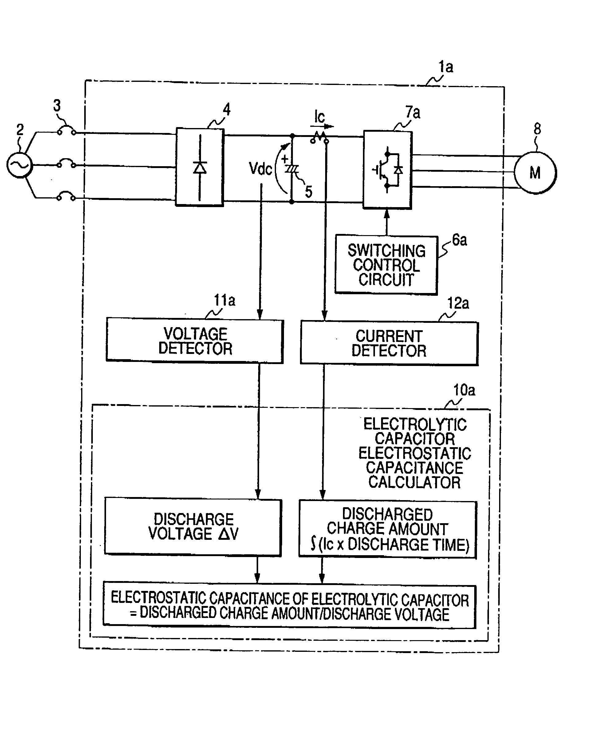
[0026] The configuration and process of an inverter device of Embodiment 1 of the invention will be described with reference to FIG. 1. Referring to FIG. 1, the inverter device 1a is connected to a commercial power source 2 through a breaker 3, a converter 4 converts the power-frequency AC voltage of the commercial power source 2 to a DC voltage, and the converted DC voltage is smoothed by an electrolytic capacitor 5. Switching elements constituting an inverter main circuit 7a are ON / OFF-controlled by a control signal from a switching control circuit 6a, whereby a DC power is converted to an AC power of predetermined frequency and voltage to drive an electric motor 8 serving as a load.

[0027] An electrolytic capacitor electrostatic capacitance calculator 10a comprises a timer which measures a discharge time in discharging of the electrolytic capacitor, and calculates the electrostatic capacitance of the electrolytic capacitor 5 on the basis of the voltage of the electrolytic capacit...

embodiment 2

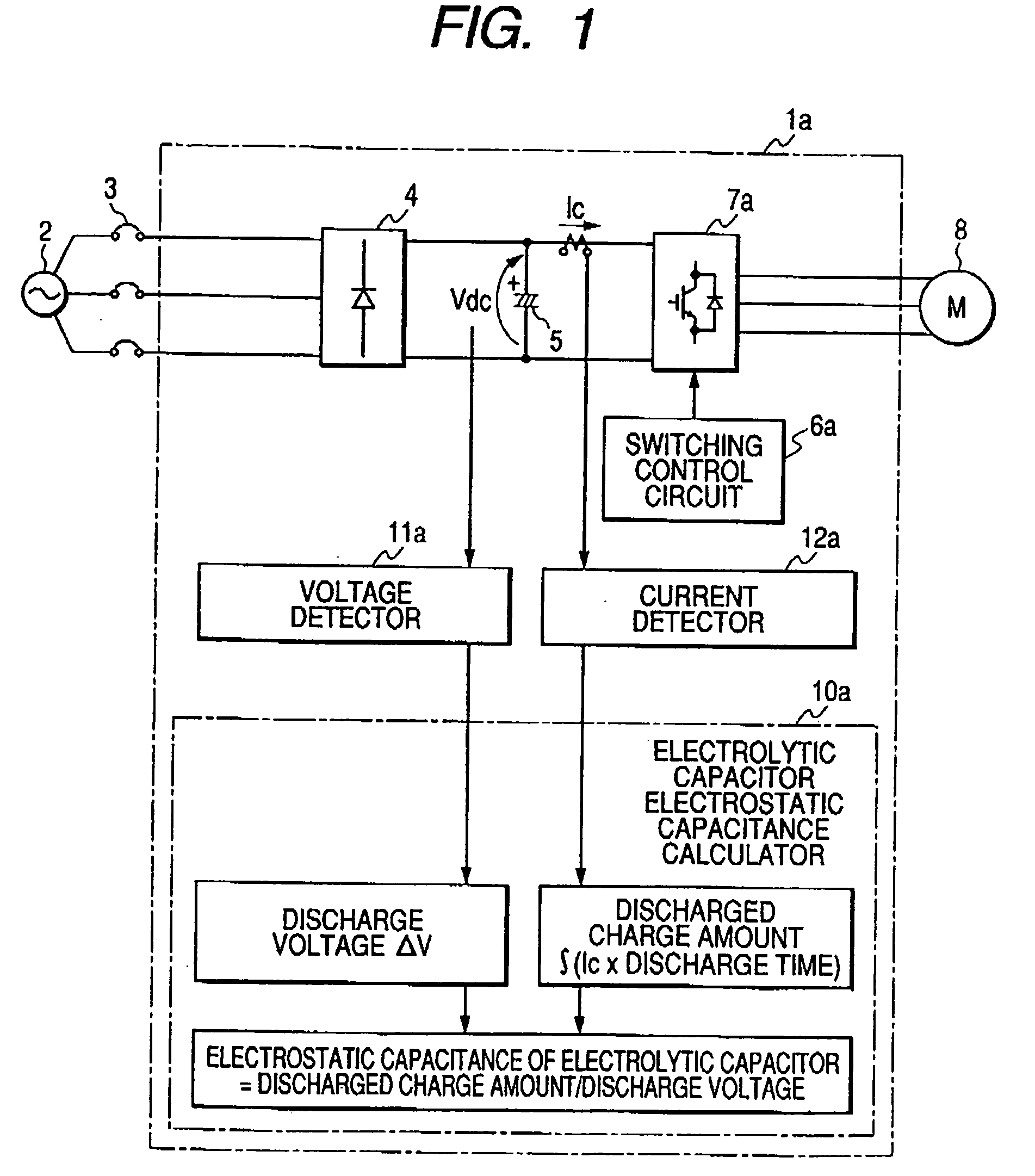
[0034] The configuration and process of an inverter device of Embodiment 2 of the invention will be described with reference to FIG. 2. In FIG. 2, 2 to 5, 6a, 7a, and 8 denote the same components as those of FIG. 1, and their description is omitted. A voltage detector 11b is configured so as to detect the voltage of the electrolytic capacitor 5, and obtain the discharge voltage ΔV which is a voltage drop from beginning of discharging. A current detector 12b is disposed for each phase of the output of the inverter main circuit 7.

[0035] An electrolytic capacitor electrostatic capacitance calculator 10b obtains a discharged charge amount of the electrolytic capacitor 5, from inverter output currents Iu, Iv, Iw of the phases detected by the current detector 12b, and a control signal which is output from the switching control circuit 6, and which is used for ON / OFF-controlling the switching elements constituting the inverter main circuit 7, and calculates the electrostatic capacitance o...

embodiment 3

[0042] The configuration and process of an inverter device of Embodiment 3 of the invention will be described with reference to FIG. 3. In FIG. 3, 5, 8, and 11a denote the same components as those of FIG. 1, and their description is omitted. When the commercial power source is interrupted, a switching control circuit 6c outputs a control signal for ON / OFF-controlling only switching elements of the U phase, and for, with respect to the V and W phases, always turning OFF upper switching elements, and always turning ON lower switching elements. A current detector 12c is disposed on the output side of the U phase (the specific one phase which is to be ON / OFF-operated when the commercial power source is interrupted).

[0043] In an inverter main circuit 7c, diode elements 13 are connected in parallel to the lower switching elements of the two phases which are always turned ON, so that a circuit configuration is formed which ensures a current path in the state where, in the specific phase w...


PUM


Abstract

In the inverter device of the invention, when a power source connected to an electrolytic capacitor 5 is interrupted, a switching control circuit 6a controls switching elements of an inverter main circuit 7a to operate to supply a current to a load, thereby discharging charges of the electrolytic capacitor 5, and an electrolytic capacitor electrostatic capacitance calculator 10a calculates the electrostatic capacitance of the electrolytic capacitor, on the basis of: a discharged charge amount which is obtained from an outflow current Ic from the electrolytic capacitor 5, and a discharge time; and a discharge voltage ΔV which is a voltage drop from beginning of discharging of the electrolytic capacitor 5.

Description

TECHNICAL FIELD [0001] The present invention relates to an inverter device in which the life of an electrolytic capacitor used in the inverter device can be determined. BACKGROUND ART [0002] As well known, an electrolytic capacitor is used in a main circuit smoothing section of a voltage source inverter device. Such an electrolytic capacitor has a limited life. Usually, when the designed time of an inverter device has elapsed, it is therefore deemed that the life of an electrolytic capacitor has expired, and the electrolytic capacitor is replaced with a new one. However, the life of an electrolytic capacitor is largely varied depending on the environment in which an inverter device is used. Therefore, there are a case where, although an electrolytic capacitor has not yet deteriorated, the capacitor is replaced with a new one after the designed constant time has elapsed, and an opposite case where, although an electrolytic capacitor has deteriorated, the life of the capacitor is not ...

Claims


Application Information

Patent Timeline
IPC IPC(8): G01R31/00G05F1/10H02M1/14H02M5/45H02M7/5387
CPCG01R31/028H02M7/53871G01R31/64H02M7/56
Inventor HATAI, AKIRAUNNO, MAHITODAIJOU, MASAKATSUEGUCHI, KIYOSHI
Owner MITSUBISHI ELECTRIC CORP
Why Eureka
Try Eureka