Method and network node for selecting a combining point

a network node and combining point technology, applied in the field of network nodes for selecting combining points, can solve the problems of increased delay, no longer centralized for all base stations in the ran, and strict power control requirements so as to achieve efficient network utilization and reduce load at the combining point

Inactive Publication Date: 2005-08-04
NOKIA CORP
View PDF8 Cites 46 Cited by
  • Summary
  • Abstract
  • Description
  • Claims
  • Application Information

AI Technical Summary

Benefits of technology

[0007] It is therefore an object of the present invention to provide a method and network node for selecting a combining point in a transmission network, by means of which the load at the combining point can be reduced and a more efficient network utilization can be achieved.

Problems solved by technology

This enables new functions such as soft handover, but also causes strict requirements on power control.
Therefore, the location of a combining point, e.g. MDC point, can no longer be centralized for all base stations in the RAN.
However, it should be possible to limit this set in order to reduce the number of MDC point relocations, which introduce additional delay, i.e., only some base stations can act as MDC points if needed.
However, if the first common upstream base station, i.e. the base station closest to the radio network gateway on the common path from a serving base station towards any drift base station, is always selected as the MDC point for the base stations that participate in soft handover, the processing load of the MDC point might be too high and network resources are not optimized.

Method used


Image

  • Method and network node for selecting a combining point
  • Method and network node for selecting a combining point
  • Method and network node for selecting a combining point

Examples


Embodiment Construction

[0040] The preferred embodiment will now be described on the basis of a new RAN network architecture for providing access to an IP network.

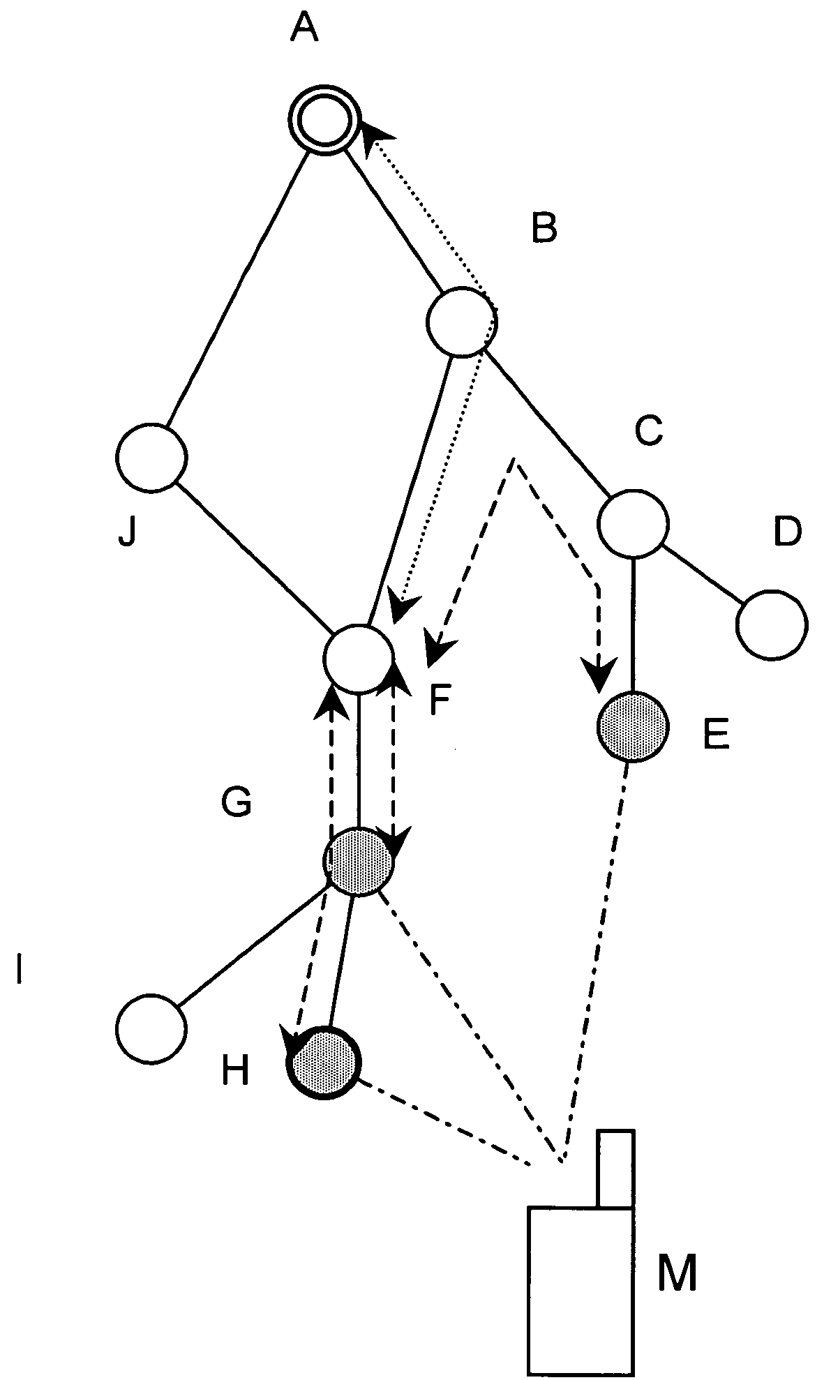
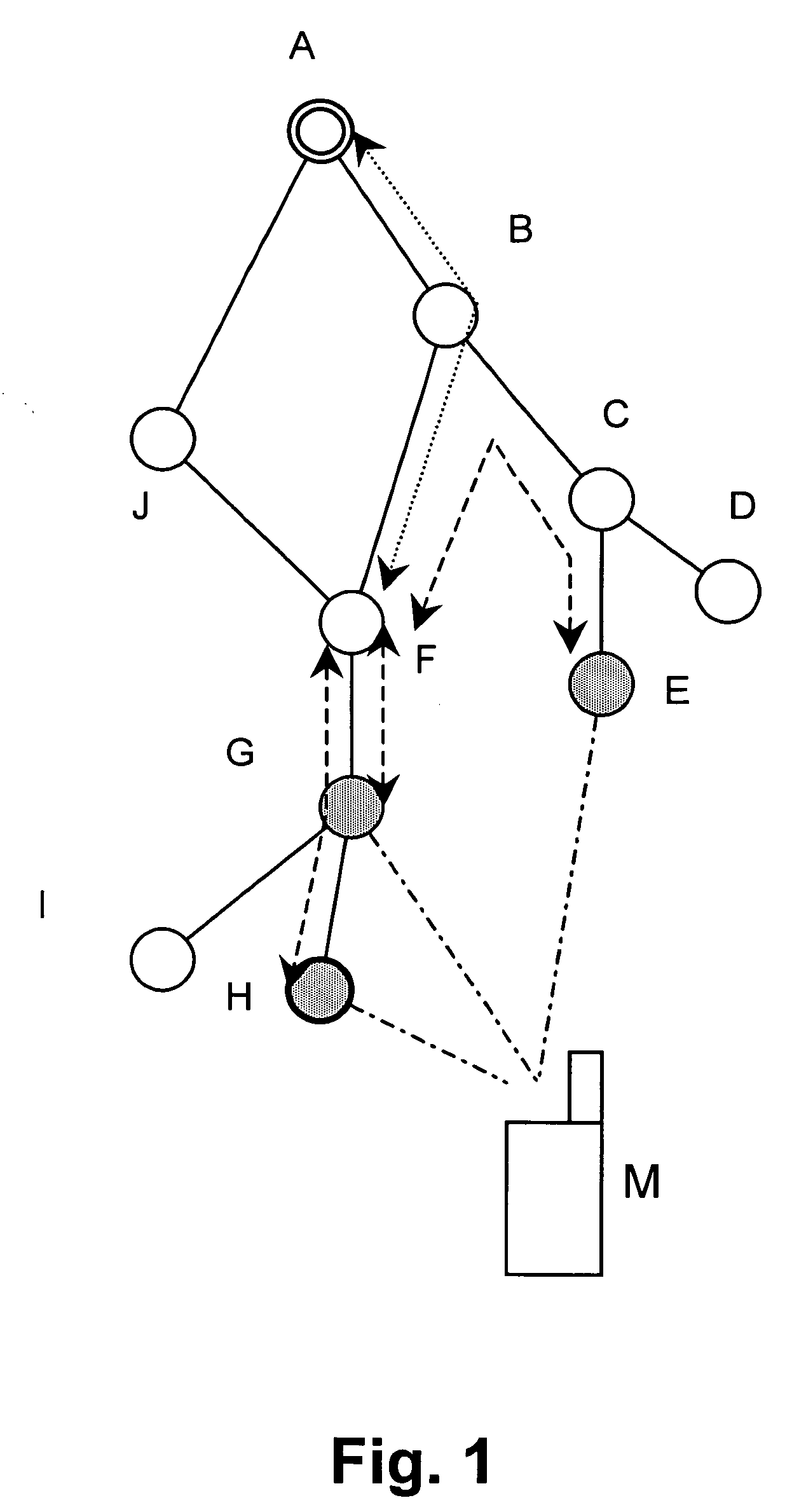
[0041] According to FIG. 1, a mobile terminal M is connected to a RAN via three redundant transmission paths indicated by respective dash-dot lines. The RAN architecture comprises a plurality of network nodes A to J, wherein the shaded nodes E, G and H are currently connected to the mobile terminal M via the redundant transmission paths. In particular, the network node H indicated with the bold circle is used as the serving base station, i.e. the base station terminating the core network interfaces data stream, and performing Radio Resource Management (RRM) functions like scheduling, power control and the like. In contrast thereto, the other shaded base stations G and E are used as drift base stations providing only resources and radio L1 layer functions for the respective connections to the mobile terminal M.

[0042] In the RAN topology shown in...


PUM


Abstract

The present invention relates to a method and network device for selecting a combining point at which at least two redundant transmission paths are combined to a single transmission path in a transmission network comprising at least two selectable combining points (B-J). The combining point is selected by a method using at least two measurement-based selection criteria to which different priorities are allocated. The selection result of a selection criterion with a higher priority is used as a constraint for a selection based on a selection criterion with a lower priority. The selection criteria are applied to lengths or loads of the redundant transmission paths or the single transmission path. Thereby, an optimized combining point can be obtained to thereby lower delays for combined traffic and increase efficiency of network utilization.

Description

FIELD OF THE INVENTION [0001] The present invention relates to a method and network node for selecting a combining point, e.g. a Macro Diversity Combining (MDC) point, at which at least two redundant transmission paths are combined to a single transmission path in a transmission network, such as a radio access network (RAN) providing access to an Internet Protocol (IP) based network architecture, comprising at least two selectable combining points. BACKGROUND OF THE INVENTION [0002] In a Code Division Multiple Access (CDMA) based cellular network all users in the same cell or in different cells may share the same frequency spectrum simultaneously. In spread spectrum transmission, the interference tolerance enables universal frequency reuse. This enables new functions such as soft handover, but also causes strict requirements on power control. Due to the universal frequency reuse, the connection of a radio terminal, e.g. a mobile terminal, mobile station or user equipment to the cell...

Claims


Application Information

Patent Timeline
Patent Type & Authority Applications(United States)
IPC IPC(8): H04L1/00H04L1/22H04L12/56
CPCH04B7/022H04W40/02H04W24/02H04L1/22
Inventor LAKKAKORPI, JANITANG, HAITAO
Owner NOKIA CORP
Why Eureka
Try Eureka