
Optical signal transmitting device

a technology of optical signal and transmission device, which is applied in the direction of electromagnetic transceivers, semiconductor laser structural details, semiconductor lasers, etc., can solve the problems of difficult inability to achieve high-speed modulation of gbps band, and general 100 mhz frequency band, etc., to achieve high optical coupling efficiency at the optically coupled portion, the effect of increasing the optical coupling efficiency with respect to optical fiber

Inactive Publication Date: 2005-08-04
FUJIFILM BUSINESS INNOVATION CORP +1
View PDF13 Cites 4 Cited by
  • Summary
  • Abstract
  • Description
  • Claims
  • Application Information

AI Technical Summary

Benefits of technology

[0009] According to the present invention, there is provided an optical signal transmitting device with which safety is ensured and high-speed modulation is possible, and whose optical coupling efficiency with respect to optical fiber is high.
[0013] Also, by limiting the divergence angle of the laser light, the optical coupling efficiency at the optically coupled portion can be maintained at a high level because the angle of incidence at the optical fiber can be made smaller.
[0014] Due to the above-described configurations of the invention, safety is ensured, high-speed modulation is possible and the optical coupling efficiency with respect to optical fiber becomes higher.

Problems solved by technology

Usually, with acrylic POF, there is little light loss with respect to visible light with a wavelength of 680 nm or less, but high-speed modulation of a Gbps band cannot be done with a visible-light light source.
For example, a light emitting diode (LED) is widely used as such a visible-light light source, but the frequency band is generally about 100 MHz and cannot accommodate high-speed modulation.
Semiconductor laser diodes (LD) are known as light sources capable of high-speed modulation, but laser light having a wavelength in the visible light region can normally be modulated to several hundred Mbps at most, and high-speed modulation of a Gbps band has been difficult.
A method of raising the light output of a semiconductor laser diode to stabilize the waveform is conceivable, but because high safety is particularly demanded for uses such as in home networks, it is necessary to use a high-output semiconductor laser diode and implement safety measures to ensure that laser safety standards are met, which leads to an increase in cost.
Even when a light source capable of high-speed modulation is used, with graded index plastic optical fiber (GI-POF) suited for high-speed modulation, there is the drawback that loss at the optically coupled portion (end portion at which the laser light is made incident) is relatively large.
However, even with the technique disclosed in that document, optical coupling efficiency cannot be raised because the incident angle at the optically coupled portion of the GI-POF cannot be adjusted.

Method used


Image

  • Optical signal transmitting device
  • Optical signal transmitting device
  • Optical signal transmitting device

Examples


example

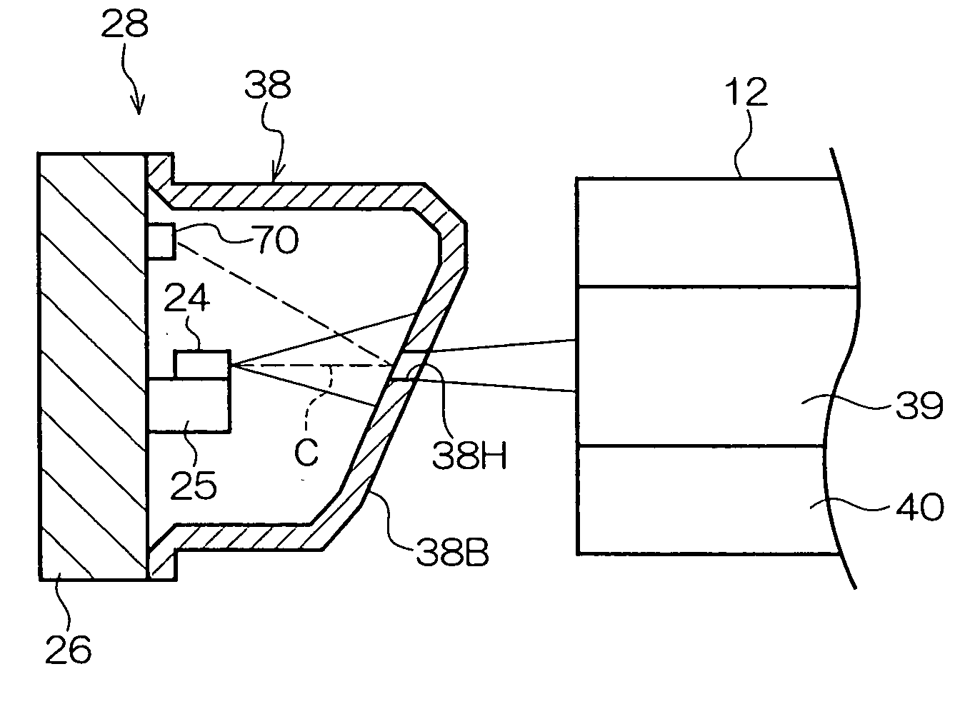
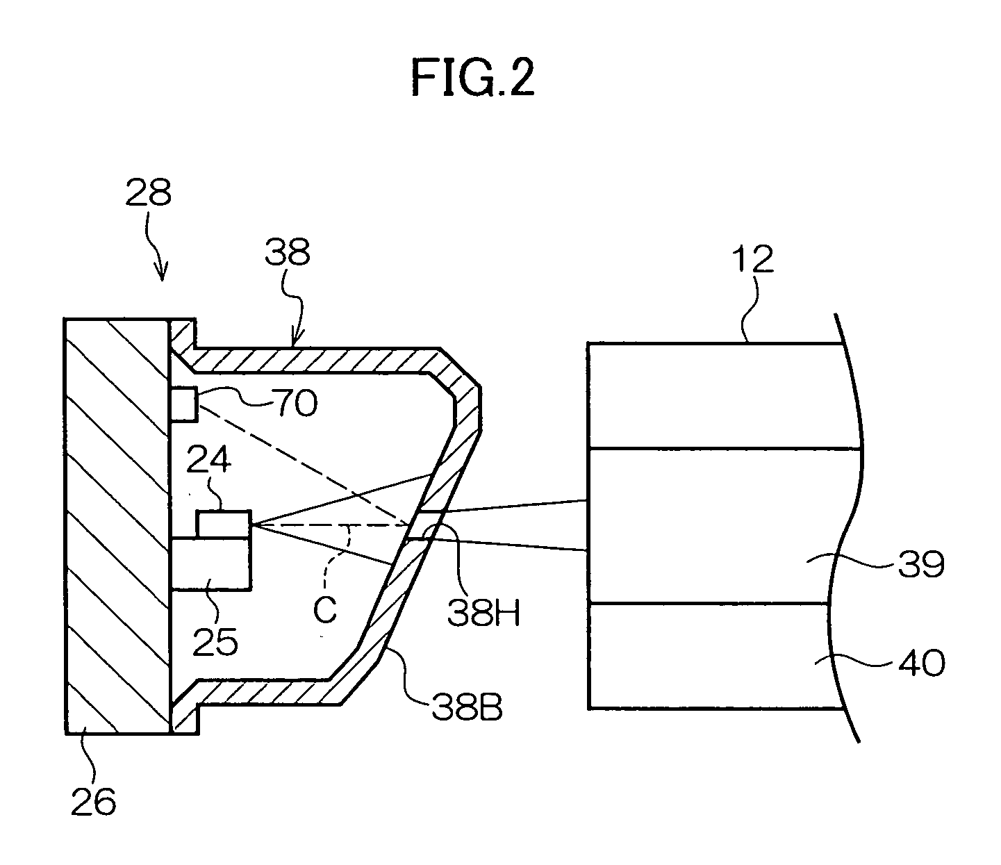
[0085] In this example, the laser light is emitted under the following conditions and transmitted by the GI-POF 39 in the optical signal transmitting device 18 of the first embodiment. [0086] Type of semiconductor laser diode: end-surface emitting semiconductor laser diode [0087] Output of semiconductor laser diode: 4.4 mW [0088] Divergence angle of laser beam from semiconductor laser diode: maximum of 30°[0089] Wavelength of laser beam: 650 nm [0090] Divergence angle after passing through light limiting member: about 7°

[0091] As a result, in the present example, the affect of relaxation oscillation is reduced, high-speed modulation at 1.25 Gbps is possible, and leakage of the light beams to the outside can be kept within a sufficient safe range. Moreover, the optical coupling efficiency becomes high and the light loss becomes small because the angle of incidence when the laser beam is made incident at the GI-POF 39 becomes about 7°, which is narrow. The intensity of the light after...


PUM


Abstract

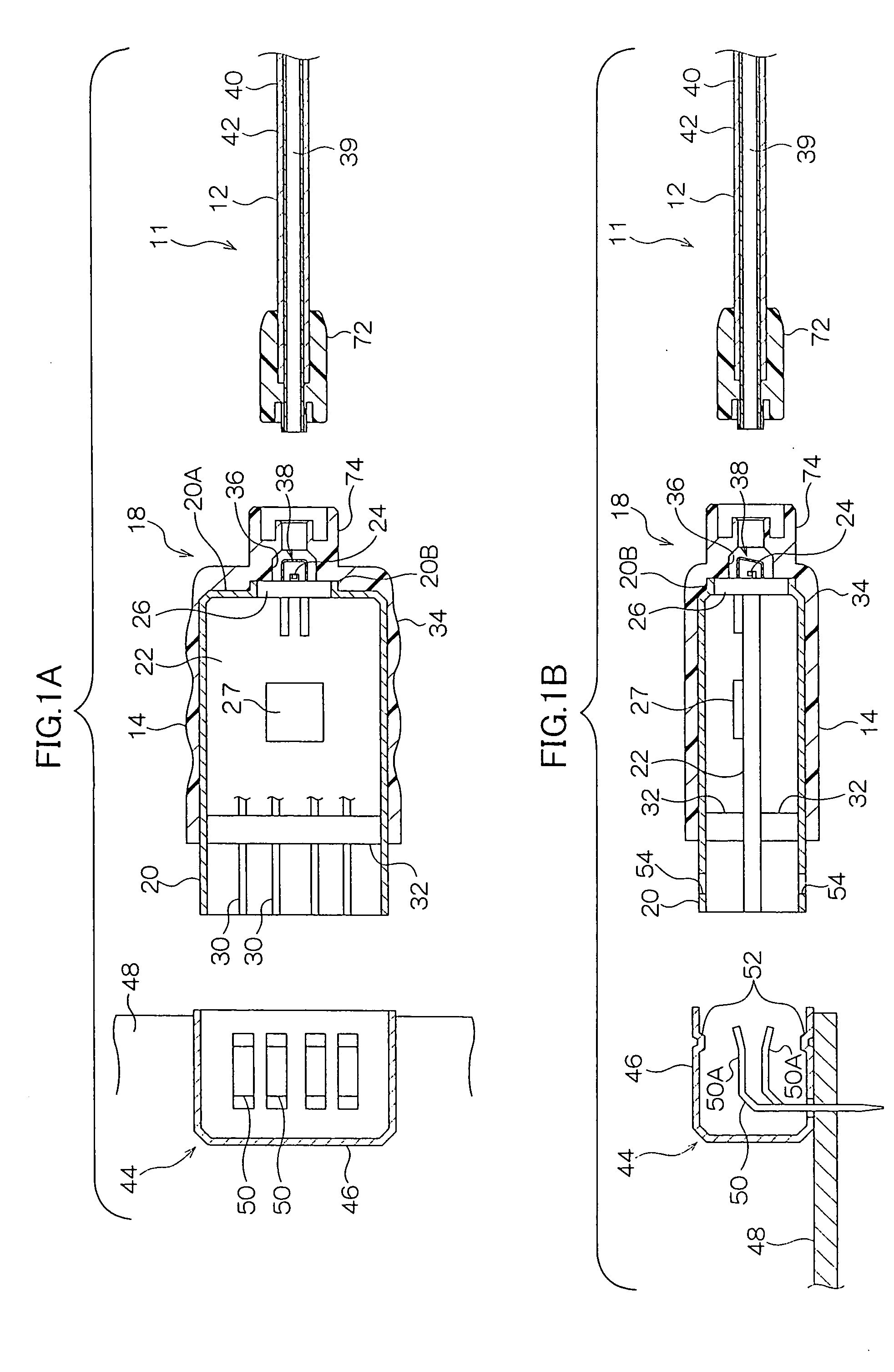
An optical signal transmitting device includes: a semiconductor laser diode that is disposed so that its periphery is covered by a laser package and which emits laser light in accordance with information to be transmitted; and a light limiting member that covers at least part of the periphery of the semiconductor laser diode and limits the light amount and divergence angle of the laser light emitted from the semiconductor laser diode. An opening is formed in a side wall of the light limiting member, and the laser light whose light amount and divergence angle have been limited by the light limiting member is guided to optical fiber connected to an optical signal device.

Description

CROSS-REFERENCE TO RELATED APPLICATION [0001] This application claims priority under 35 USC 119 from Japanese Patent Application No. 2003-385495, the disclosure of which is incorporated by reference herein. BACKGROUND OF THE INVENTION [0002] 1. Field of the Invention [0003] The present invention relates to an optical signal transmitting device for transmitting optical signals. [0004] 2. Description of the Related Art [0005] Conventionally, in small-scale networks such as so-called home networks, the utilization of acrylic (e.g., polymethyl methacrylate; abbreviated as PMMA below) plastic optical fiber (POF) for optical fiber serving as a transmission line has been expected because it is safe and inexpensive. Usually, with acrylic POF, there is little light loss with respect to visible light with a wavelength of 680 nm or less, but high-speed modulation of a Gbps band cannot be done with a visible-light light source. For example, a light emitting diode (LED) is widely used as such a ...

Claims


Application Information

Patent Timeline
Patent Type & Authority Applications(United States)
IPC IPC(8): H01S5/02H01S5/022H01S5/0683H04B10/079H04B10/2507H04B10/40H04B10/50H04B10/60
CPCH01S5/02284H04B10/503H01S5/0683H01S5/02296H01S5/02251H01S5/02257
Inventor UENO, OSAMUMIURA, MASAAKIMATSUMOTO, KENJIHIIRO, HIROYUKI
Owner FUJIFILM BUSINESS INNOVATION CORP
Learn More