Thermal barrier coating system

a coating system and thermal barrier technology, applied in the direction of surface reaction electrolytic coating, liquid fuel engine components, non-positive displacement fluid engine, etc., can solve the problem of particularly demanding requirements, achieve inferior erosion resistance, and improve the spallation resistance of the tbc system, the effect of high surface temperatur

Active Publication Date: 2005-08-04
GENERAL ELECTRIC CO
View PDF8 Cites 110 Cited by
  • Summary
  • Abstract
  • Description
  • Claims
  • Application Information

AI Technical Summary

Benefits of technology

[0011] A significant advantage of this invention is that it provides a TBC system suitable for protecting the surfaces of gas turbine engine components when subjected to surface temperatures that exceed the phase transformation temperature of conventional 6-8% YSZ. More particularly, because the second ceramic layer of fully-stabilized zirconia does not undergo a phase transformation, the second ceramic layer can withstand the high surface temperatures that occur when thick TBC's (e.g., in excess of 500 micrometers) are subjected to the hot gas path of a gas turbine engine. Though fully-

Problems solved by technology

This requirement is particularly demanding due to the different coefficients of thermal expansio

Method used


Image

  • Thermal barrier coating system
  • Thermal barrier coating system

Examples


Embodiment Construction

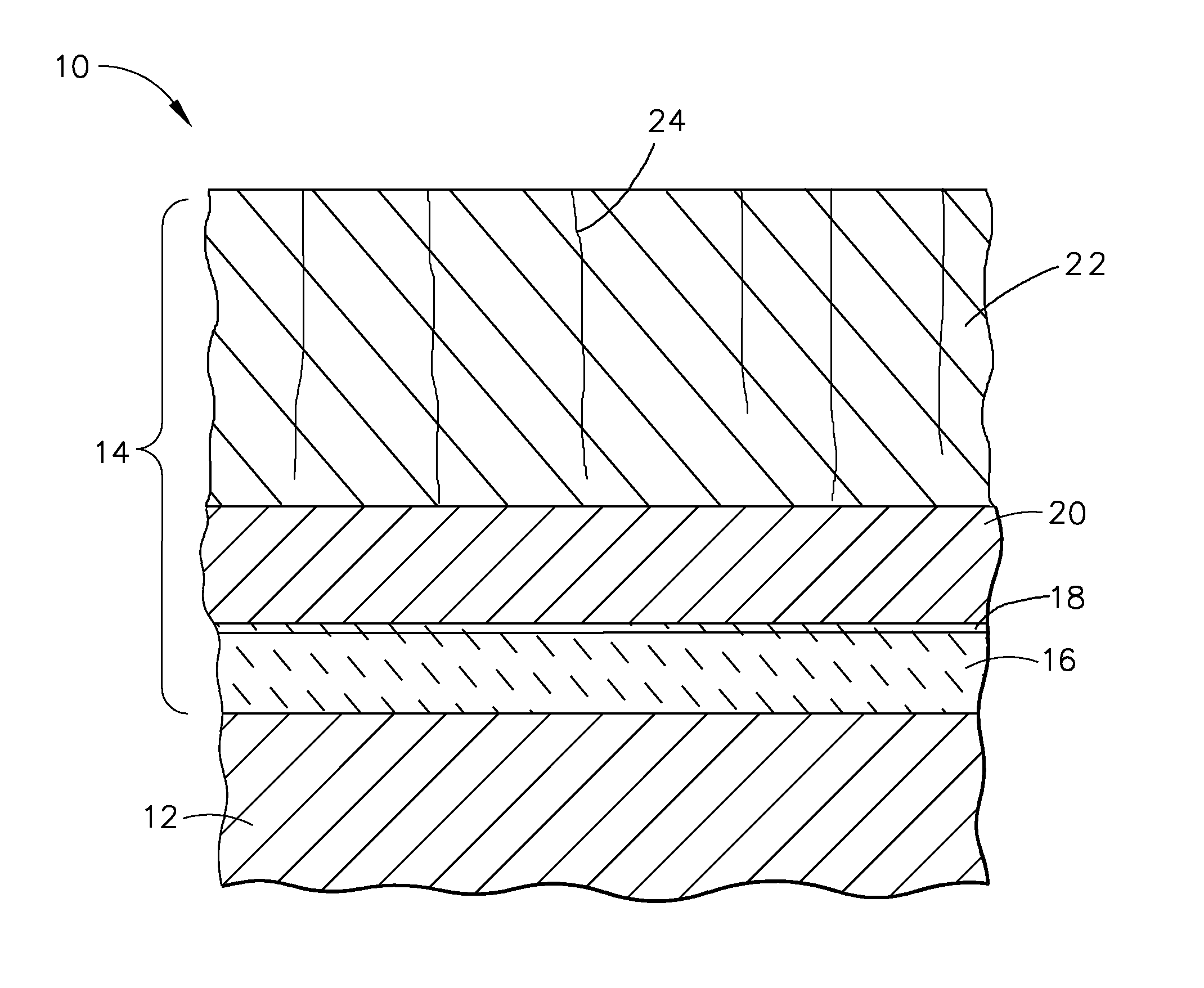
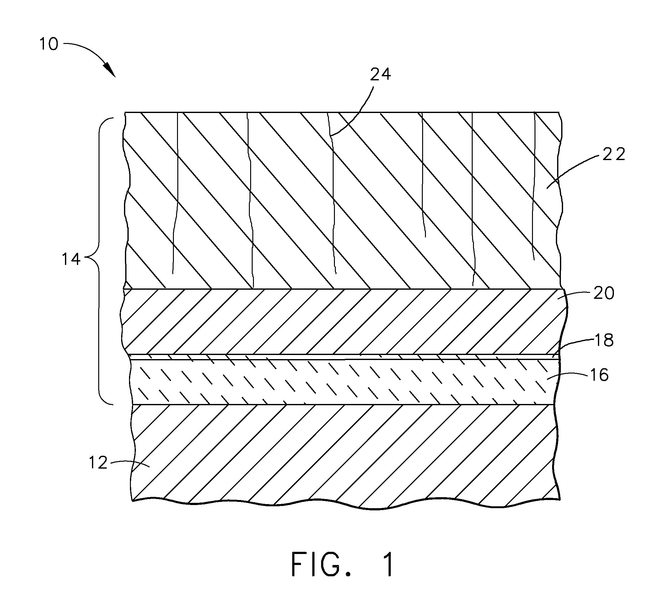
[0014] The present invention is generally applicable to components subjected to high temperatures, and particularly to components such as the combustor liners and the high pressure turbine (HPT) shrouds of gas turbine engines. While the advantages of this invention will be described with reference to gas turbine engine components, the teachings of the invention are generally applicable to any component on which a TBC may be used to protect the component from a high temperature environment.

[0015]FIG. 1 schematically represents a surface region of a component 10 protected by a TBC system 14 in accordance with a preferred embodiment of the invention. The TBC system 14 (not to scale) is shown as including a bond coat 16 overlying the surface of a substrate 12, the latter of which is preferably a superalloy or another high temperature material. The substrate 12 is typically the base material of the component 10 protected by the coating system 14, though the substrate 12 may instead be a...


PUM

PropertyMeasurementUnit
Lengthaaaaaaaaaa
Lengthaaaaaaaaaa
Percent by massaaaaaaaaaa

Abstract

A TBC system suitable for protecting the surface of a substrate subjected to a hostile thermal environment. The TBC system comprises a bond coat on the substrate surface, an alumina scale on the bond coat, and a multilayer TBC comprising a thermal-sprayed first ceramic layer on the alumina scale and a thermal-sprayed second ceramic layer overlying the first ceramic layer. The first ceramic layer consists essentially of partially stabilized zirconia so as to comprise the tetragonal and cubic phases of zirconia. The second ceramic layer consists essentially of fully stabilized zirconia so as to consist essentially of the cubic phase of zirconia. The second ceramic layer is also characterized by having vertical microcracks that extend through the thickness thereof. The second ceramic layer is thicker and more erosion resistant than the first ceramic layer.

Description

BACKGROUND OF INVENTION [0001] 1. Field of the Invention [0002] The present invention generally relates to thermal barrier coating systems for components exposed to high temperatures, such as gas turbine engine combustor liners and shrouds. More particularly, this invention is directed to a thermal barrier coating system having a multilayer thermal barrier coating comprising a spallation-resistant inner layer and a phase-stable outer layer. [0003] 2. Description of the Related Art [0004] Components within the hot gas path of a gas turbine engine are often protected by a thermal barrier coating (TBC) system. TBC systems include a thermal-insulating topcoat, also referred to as the thermal barrier coating or TBC. Ceramic materials are used as TBC materials because of their high temperature capability and low thermal conductivity. The most common TBC material is zirconia (ZrO2) partially or fully stabilized by yttria (Y2O3), magnesia (MgO) or another alkaline-earth metal oxide, ceria (...

Claims


Application Information

Patent Timeline
IPC IPC(8): B32B15/04
CPCC23C4/085C23C4/10C23C4/127C23C28/321C23C28/3215Y10T428/12611C23C28/3455C23C28/36Y02T50/67Y10T428/1259Y10T428/12618C23C28/345C23C4/073C23C4/134Y02T50/60
Inventor NAGARAJ, BANGALORE A.DAROLIA, RAMGOPAL NMN
Owner GENERAL ELECTRIC CO
Why Eureka
Try Eureka