
Method for decomposing plastic composite

a plastic composite and decomposing technology, applied in the field of decomposing plastic composites, can solve the problems of difficult recycling of plastic composite waste materials, thermosetting resin and reinforcing fibers cannot be easily separated once cured, etc., and achieve the effect of efficient processing

Pending Publication Date: 2021-05-06
MITSUBISHI HEAVY IND LTD
View PDF0 Cites 0 Cited by
  • Summary
  • Abstract
  • Description
  • Claims
  • Application Information

AI Technical Summary

Benefits of technology

The present disclosure describes a method for processing plastic composites by using inorganic oxide catalysts. Even at low temperatures, the catalysts can oxidize hydrocarbon and carbon monoxide in the gas generated by the decomposition of the plastic composite's matrix resin, resulting in a high surface temperature of the plastic composite. This allows for efficient processing while maintaining the strength of the composite. The surface temperature of the composite is controlled to prevent deterioration and facilitate recycling. The method is particularly effective at low temperatures by using a granular shape or a combination of granular and honeycomb shapes as the catalyst or disposing the layered surfaces of the plastic composite in contact with the catalyst.

Problems solved by technology

Since it is difficult to recycle waste materials of plastic composites such as carbon fiber reinforced plastics (CFRP) with the current technology, most of the waste materials are landfilled or incinerated.
In particular, in a case where a thermosetting resin such as an epoxy resin is used as a matrix of the plastic composite, the thermosetting resin and reinforcing fiber cannot be easily separated once cured.

Method used


Image

  • Method for decomposing plastic composite
  • Method for decomposing plastic composite
  • Method for decomposing plastic composite

Examples


example 1

Catalyst

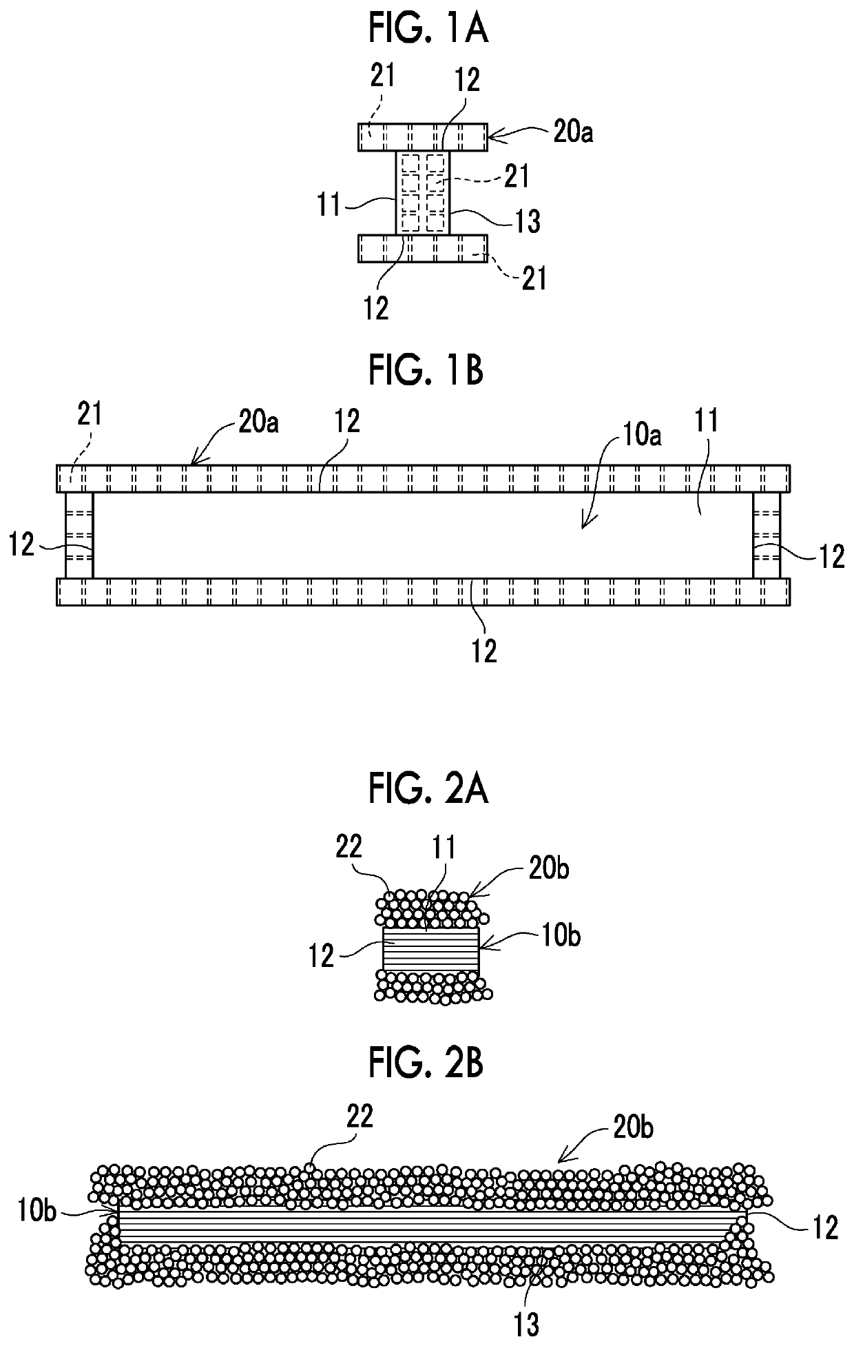
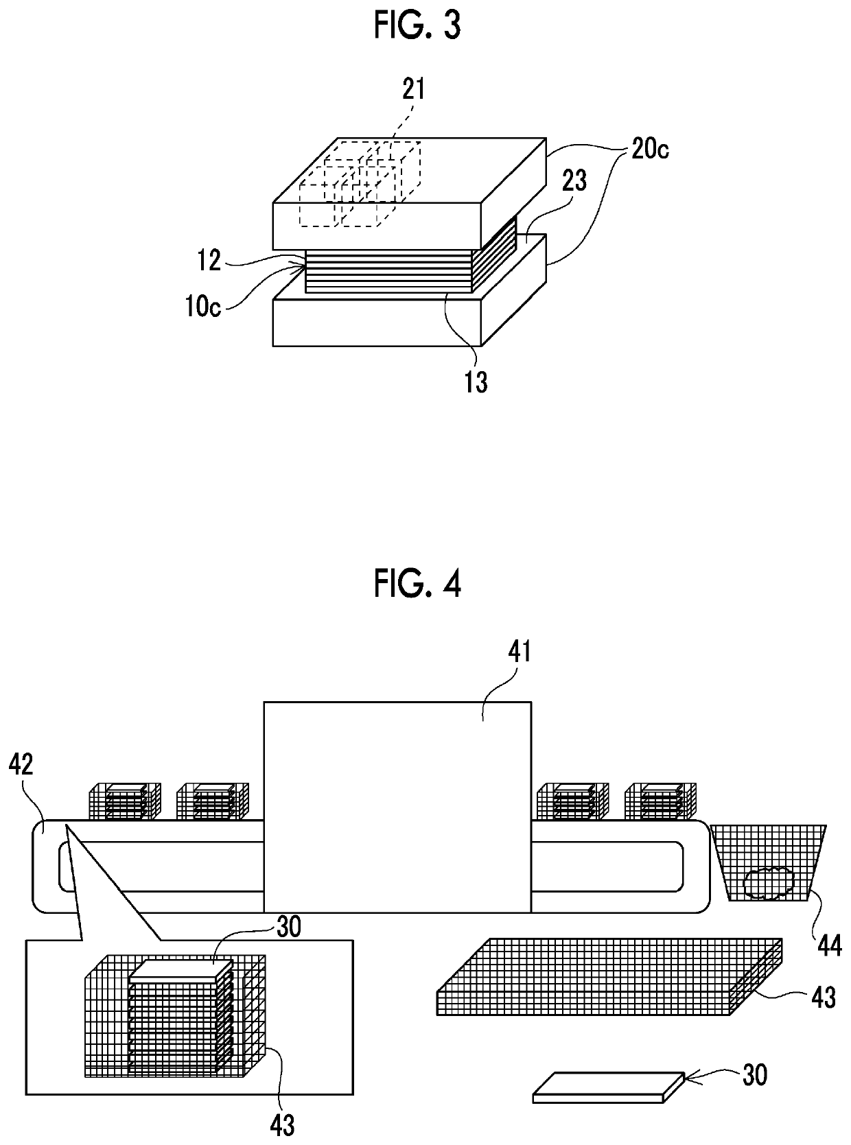
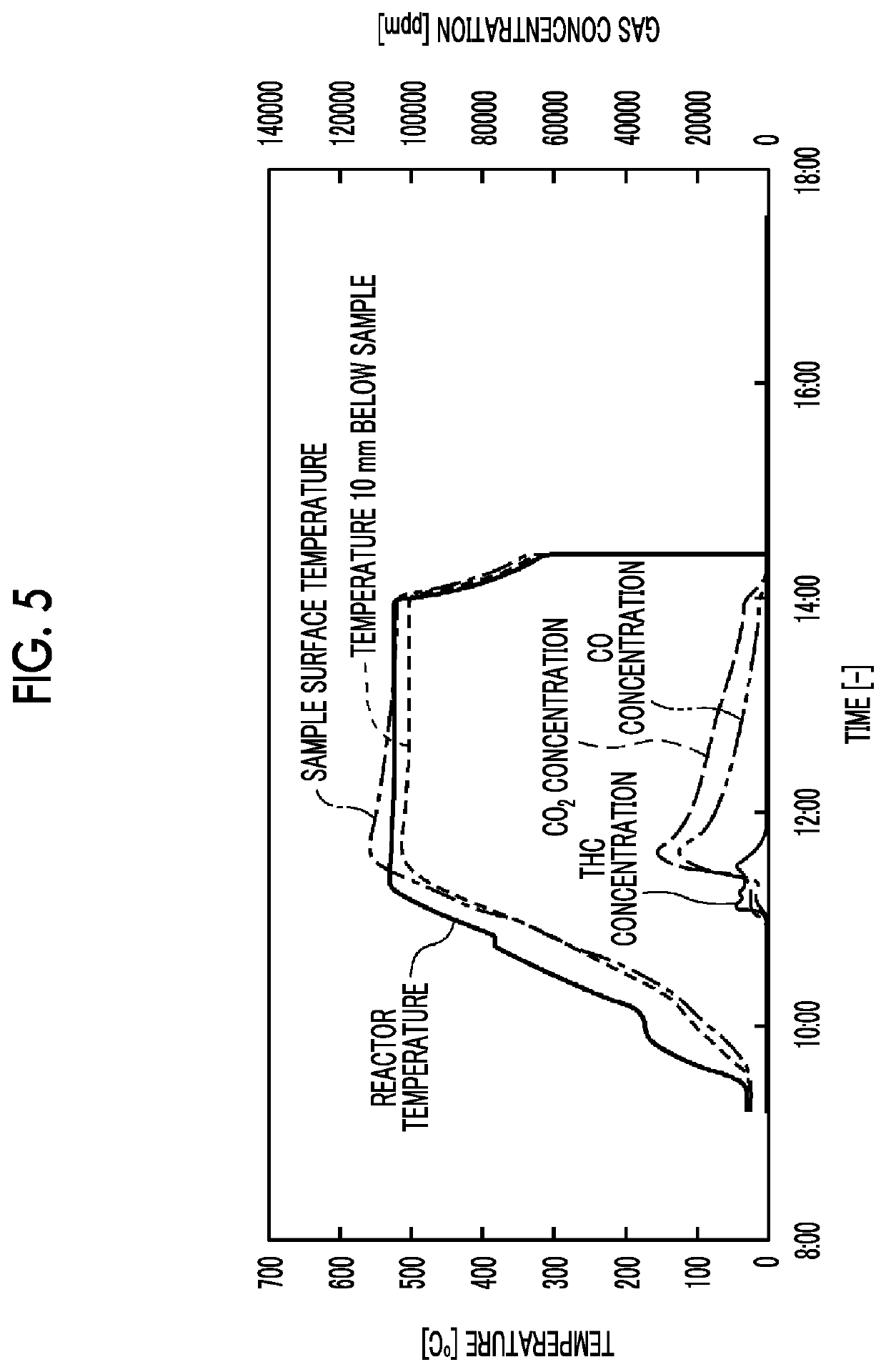
[0041]Tests were performed to decompose the plastic composite using various catalysts. As the plastic composite, a carbon fiber reinforced resin having a size of width 30 mm×length 200 mm×height 12 mm and epoxy resin as the matrix resin was used. As the catalyst, no catalyst used in Test Example 1, and a honeycomb type denitration catalyst (a ternary catalyst of TiO2 / V2O5 / WO3 or MoO3) with a cell size of 6.4 mm×6.4 mm×10 mm) was used in Test Example 2. In Test Example 3, a TiO2 granular catalyst (CS-200S-24 manufactured by SAKAI CHEMICAL CO., LTD., diameter: 2 to 4 mm) was used as it was. In Test Example 4, CuO (special grade reagent manufactured by KANTO CHEMICAL CO., INC.) was pressure-formed, crushed, rectified into granular shapes having a diameter of 2 to 4 mm, and then used.

[0042]In a case where the honeycomb type denitration catalyst was used, as illustrated in FIGS. 1A and 1B, all the four side surfaces, which are the layered surfaces of the plastic composite, were d...

example 2

hip Between Band Gap and Performance of Catalyst at Setting Temperature of 400° C.

[0049]5 g of respective granular catalysts (diameter of 2 to 4 mm) having Cr2O3, CuO, amorphous α-Al2O3 (alpha type alumina), V2O5, and TiO2 (anatase type) having different band gaps were placed on the front surface of 2 g of the plastic composite that is the same material as in Example 1, and tests were performed in the atmosphere with the setting temperatures of 400° C. and the holding time of 1.5 hours. Additionally, as a comparative example, a test was performed under the same conditions even in a case where the catalyst was not placed. The results are shown in FIG. 9. In addition, the vertical axis of the graph in FIG. 9 was not the weight decrease rate (%), but a weight decrease rate ratio (unit: none) that is the ratio of weight decrease rates of the respective catalysts in a case where the weight decrease rate in a comparative example without a catalyst was set to 1.

[0050]As illustrated in FIG....

example 3

ce of Denitration Catalyst at Setting Temperature of 400° C.

[0051]Regarding the honeycomb type denitration catalyst of Test Example 2 of Example 1 that is a TiO2-based catalyst, a test was performed under the same conditions as in Example 1 except that the setting temperature of the reactor was set to 400° C., gas (O2: 21 vol %, H2O: 1.38 vol %, N2: the balance) was caused to flow at a flow rate of 1 NL / min, the holding time was set to 4.5 hours, and the weight of the plastic composite during the test was continuously measured. In addition, as a comparative example, a test was performed under the same conditions even in a case where no catalyst was placed. The results are shown in FIG. 10. In addition, the right vertical axis of the graph of FIG. 10 represents a weight change ratio (unit: none) that is the ratio of a change in the weight of the plastic composite after the temperature rising time of 200 minutes with respect to the weight of the plastic composite before the test in th...


PUM

PropertyMeasurementUnit
band gapaaaaaaaaaa
atmospheric temperatureaaaaaaaaaa
surface temperatureaaaaaaaaaa

Abstract

Provided is a method for decomposing a plastic composite with which it is possible to sufficiently decompose the matrix resins of the plastic composite in a short time even when the heating temperature of the plastic composite is low. In this method for decomposing a plastic composite, the plastic composite is brought into contact with an inorganic oxide catalyst having a band gap of 4 eV or less in a reactor, and the atmospheric temperature in the reactor is set at 380 to 530° C. in the presence of oxygen, and the surface temperature of the plastic composite is 480 to 650° C., which is at least 50° C. higher than the atmospheric temperature.

Description

TECHNICAL FIELD[0001]The present invention relates to a method for decomposing a plastic composite.BACKGROUND ART[0002]Since it is difficult to recycle waste materials of plastic composites such as carbon fiber reinforced plastics (CFRP) with the current technology, most of the waste materials are landfilled or incinerated. In particular, in a case where a thermosetting resin such as an epoxy resin is used as a matrix of the plastic composite, the thermosetting resin and reinforcing fiber cannot be easily separated once cured.[0003]Thus, a thermal decomposition method or a thermal semiconductor method has been developed as a technique for processing or recycling the plastic composite. For example, PTL 1 describes, as the thermal semiconductor method, a method for processing a plastic composite, in which a polymer of the plastic composite is decomposed by bringing a catalyst carrying honeycomb in which a semiconductor such as chromium oxide or titanium oxide is carried on the front s...

Claims


Application Information

Patent Timeline
Patent Type & Authority Applications(United States)
IPC IPC(8): C08J11/16B01J21/06B01J23/72B01J35/04B01J35/02
CPCC08J11/16B01J21/063B01J35/026B01J35/04B01J23/72B01J23/28B01J23/30Y02W30/62B29B2017/0496B29B17/04B29K2105/06B01J2523/00B01J35/50B01J35/56B01J2523/47B01J2523/55B01J2523/69B01J2523/68
Inventor NOCHI, KATSUMI
Owner MITSUBISHI HEAVY IND LTD
Learn More