Device for a hydraulic cutting tool

a cutting tool and hydraulic technology, applied in the direction of directional drilling, sealing/packing, borehole/well accessories, etc., can solve the problems of gas bubbles having a disruptive or damaging effect, gas bubbles rising, etc., to achieve reduce the effect of gas bubbles, and improve the likelihood of achieving efficient and successful hydraulic cutting

Active Publication Date: 2005-08-11
OCEANEERING NCA
View PDF10 Cites 44 Cited by
  • Summary
  • Abstract
  • Description
  • Claims
  • Application Information

AI Technical Summary

Benefits of technology

[0024] By using a device according to the invention it is avoided that gas bubbles rising through the liquid column of the pipe and causing any disruptive or damaging movement of the hydraulic cutting tool, which would have a negative effect on the result of the hydraulic cutting.
[0025] Moreover, use of the present device allows a small pipe volume under the cutting tool to be filled, in a controlled manner, with gas at a significantly higher pressure than the hydrostatic pressure at the cutting si...

Problems solved by technology

As mentioned, this leads to gas bubbles rising through the liquid column of the pipe, and ...

Method used


Image

  • Device for a hydraulic cutting tool
  • Device for a hydraulic cutting tool
  • Device for a hydraulic cutting tool

Examples


Embodiment Construction

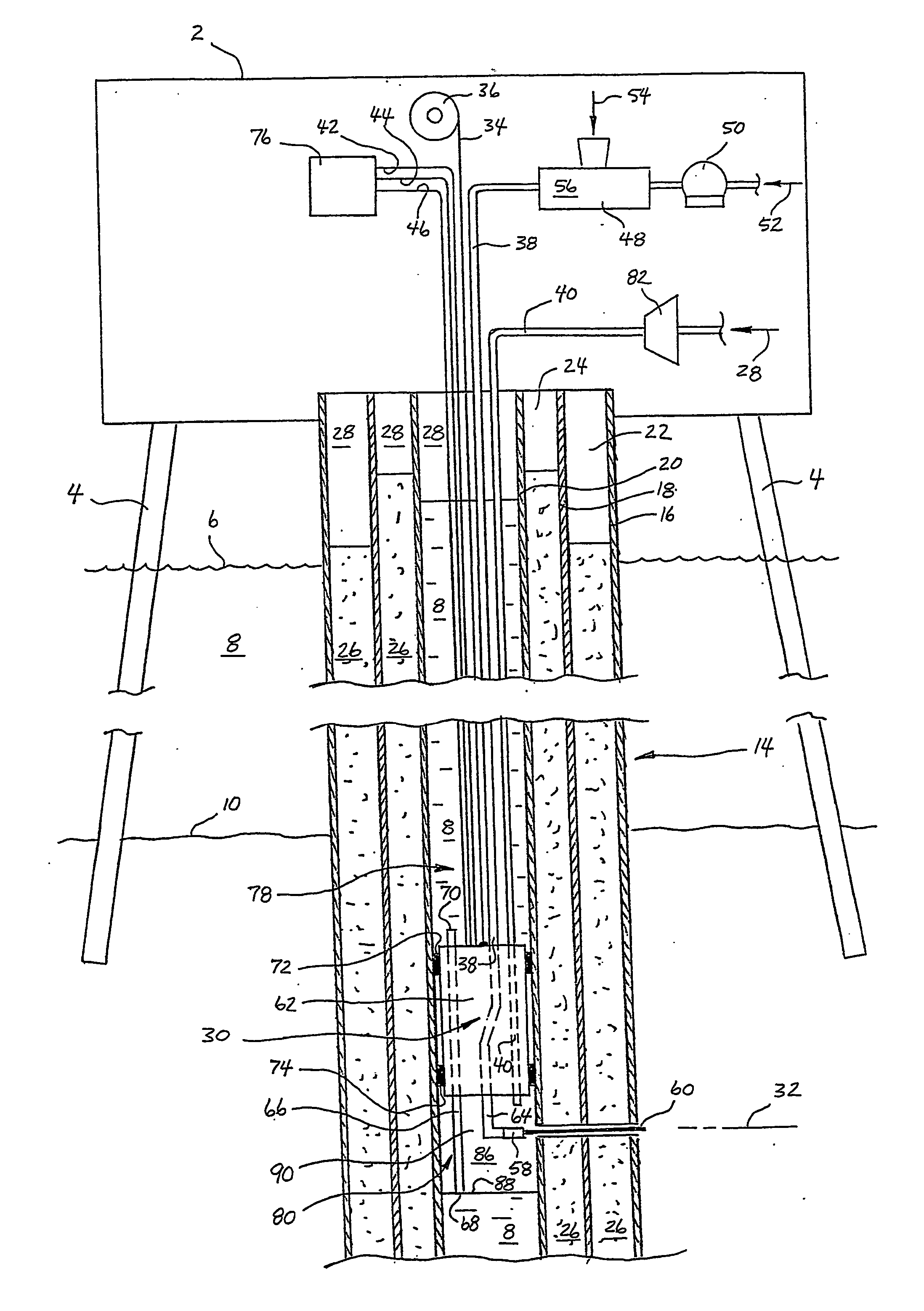
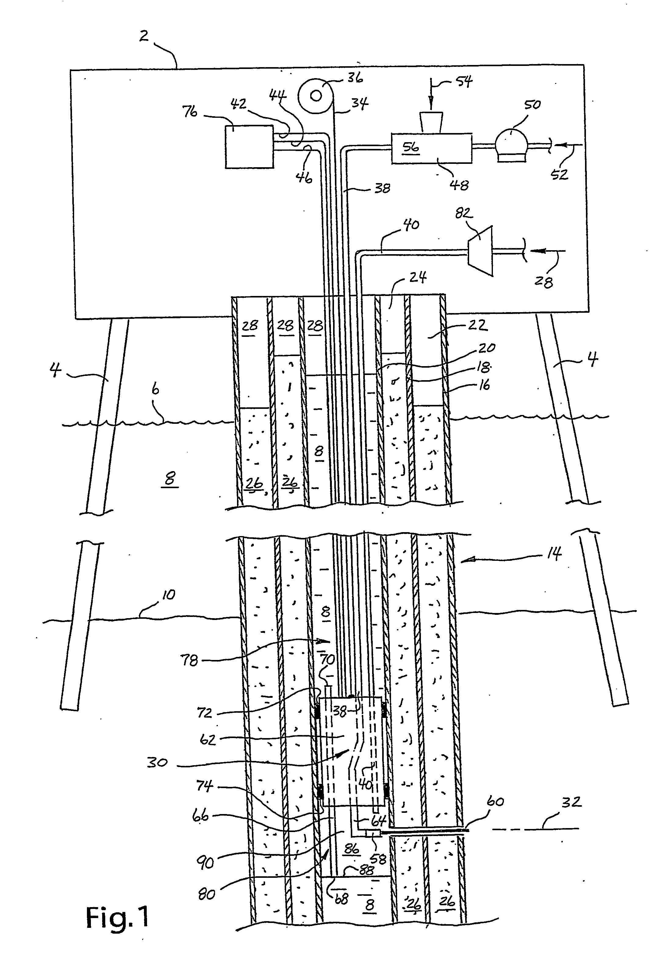
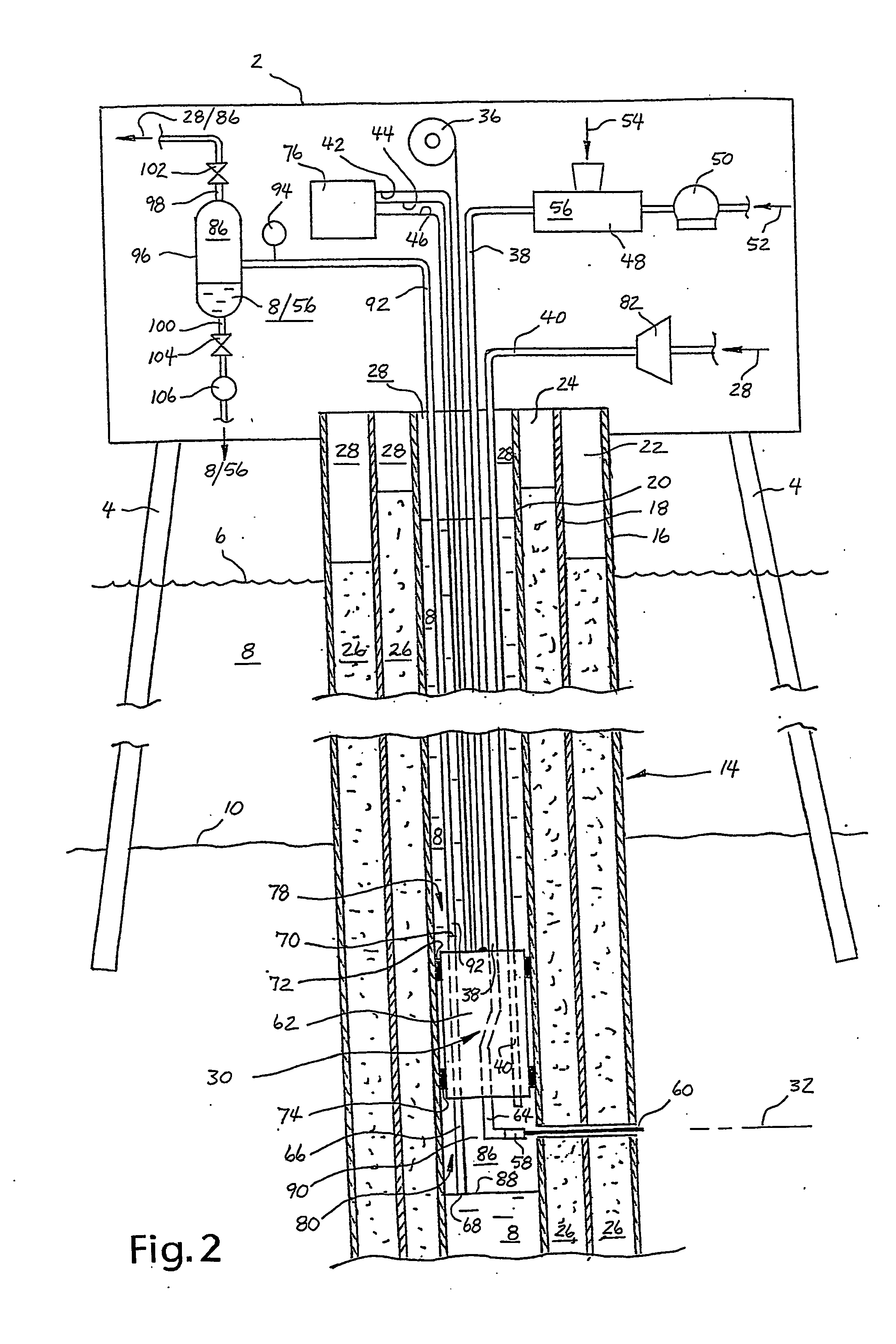
[0031] The following examples concerns hydraulic cutting of the casing of a well beneath a water floor in connection with permanent plugging and abandonment of the well.

[0032]FIG. 1 and FIG. 2 show an offshore platform 2 installed on the sea floor, which platform is equipped with platform legs 4, and which is arranged over a surface 6 of the sea. The platform legs 4 extend through seawater 8 down to a sea floor 10 where they penetrate an underlying ground formation 12. An offshore well 14 is formed in the ground formation 12 and extends up to the platform 2. Such a platform 2 will normally be tied in to more offshore wells 14, but the figures and the following discussion are simplified by referring only to one offshore well 14.

[0033] Before the well 14 is permanently abandoned, all removable equipment is removed from the well 14, including the wellhead and all or parts of the production tubing. After that, the well 14 consists only of casing strings that are permanently placed in ...


PUM

PropertyMeasurementUnit
Pressureaaaaaaaaaa
Flow rateaaaaaaaaaa
Volumeaaaaaaaaaa

Abstract

A device for a hydraulic cutting tool (30) for cutting of at least one pipe (16, 18, 20) or tubular object beneath a water floor (10), wherein the cutting is carried out from a surface facility (2). The cutting tool (30) is anchored in a pressure tight manner in the pipe (16), whereupon pressurised gas (86) is pumped into a pipe section (80) immediately below the cutting tool (30). With this, liquid (8), and eventually pressurised gas (86), will flow out of the pipe section (80) via a short drain pipe (66) through the cutting tool (30), so as to create a gas filled pipe volume (90) comprising the relevant cutting depth (32) in the pipe section (80). The invention differs from prior art by the outflowing liquid being led onwards up to the surface facility (2) via a drain line (92). The upper end portion of the drain line (92) is connected to at least one adjustable choke device (102, 104). This allows the gas overpressure in said pipe volume (90) to be controlled during the cutting, providing optimal operating conditions during the hydraulic cutting.

Description

BACKGROUND OF INVENTION [0001] 1. Field of Invention [0002] This invention regards a device for a hydraulic cutting tool for cutting of tubular objects beneath a water floor, e.g. beneath a seafloor. [0003] The device is preferably used for cutting of casings in connection with the permanent plugging and abandonment of a well drilled under water, e.g. a petroleum well. After cutting, the cut-off pieces of casing may be removed from the water floor. Such a well may be completed at the water floor or above water, e.g. on a platform or another type of surface facility. In the latter case the well is connected to the surface facility via a riser. On the other hand, both types of wells are drilled under water and down into a water floor, and such a well is hereinafter termed an offshore well. [0004] Said device may also be used in connection with the cutting of other types of tubular objects disposed in a water floor. Such an object may comprise a tubular pile or a caisson. As an example...

Claims


Application Information

Patent Timeline
IPC IPC(8): E02D9/00E21B29/12
CPCE21B29/12E02D9/005
Inventor LUND, PERWIIG, ERLING J.
Owner OCEANEERING NCA
Why Eureka
Try Eureka