Field effect transistor amplifier with linearization

a transistor amplifier and field effect technology, applied in the direction of low noise amplifier, amplifier modification to reduce non-linear distortion, transmission, etc., can solve the problems of higher noise factor, not widely adopted, and inability to cancel feed-forward distortion

Active Publication Date: 2005-08-11
QUALCOMM INC
View PDF8 Cites 70 Cited by
  • Summary
  • Abstract
  • Description
  • Claims
  • Application Information

AI Technical Summary

Benefits of technology

[0007] In accordance with an embodiment of an illustrative communication apparatus, an amplifier comprises a source degeneration inductance and at least two field effect transistors coupled in parallel and having mutually different gate biasing. Source connections of the field effect transistors are coupled along different positions of the source degeneration inductance.

Problems solved by technology

Feed-forward distortion cancellation has not been widely adopted because of high sensitivity to mismatches between main and auxiliary gain stages and errors in input signal scaling.
One disadvantage of the derivative superposition technique is a resulting higher noise factor, for example in a range of about 0.6 dB.

Method used


Image

  • Field effect transistor amplifier with linearization
  • Field effect transistor amplifier with linearization
  • Field effect transistor amplifier with linearization

Examples


Embodiment Construction

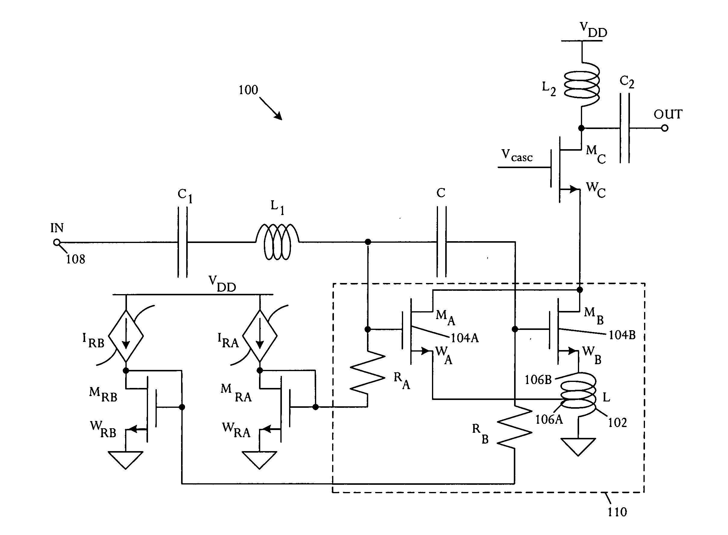
[0017] A novel modified derivative superposition method attains a very high third-order intercept point IIP3 at radio frequency. The illustrative derivative superposition method creates opposing phases of second and third-order contributions to third-order intermodulation distortion (IMD3) by using a controlled inductance for source degeneration of a composite field-effect transistor. In an illustrative embodiment, the modified derivative superposition method implements a tapped inductor for source degeneration. The modified method increases third-order intercept point IIP3 of a low noise amplifier embodiment. In a specific implementation, IIP3 is boosted by 15 dB.

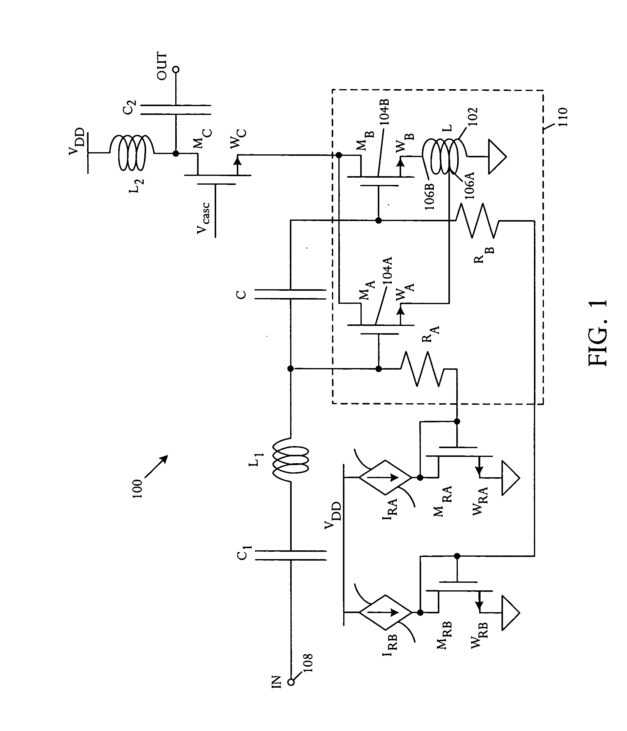
[0018] Referring to FIG. 1, a schematic circuit diagram illustrates an amplifier 100 that comprises a source degeneration inductance 102 and at least two field effect transistors 104A, 104B coupled in parallel and having mutually different gate biasing. Source connections of the field effect transistors are coupled along ...


PUM


Abstract

An amplifier comprises a source degeneration inductance and at least two field effect transistors coupled in parallel and having mutually different gate biasing. Source connections of the field effect transistors are coupled along different positions of the source degeneration inductance.

Description

RELATED APPLICATIONS [0001] This application claims priority to U.S. Provisional Application No. 60 / 544,282, filed Feb. 11, 2004.BACKGROUND OF THE INVENTION [0002] Receivers in communication systems commonly incorporate one or more low noise amplifiers (LNAs) with suitable performance characteristics. For example single-tone desensitization for code division multiple access (CDMA) telephones generally specify a very high LNA third-order intercept point IIP3 in combination with low noise factor (NF), high gain, and low current consumption. Linearization techniques are commonly used to attain appropriate performance. [0003] For example, feed-forward distortion cancellation has been used to attain a very high IIP3 for a complementary metal-oxide semiconductor (CMOS) low noise amplifier. Feed-forward distortion cancellation has not been widely adopted because of high sensitivity to mismatches between main and auxiliary gain stages and errors in input signal scaling. [0004] A field-effec...

Claims


Application Information

Patent Timeline
Patent Type & Authority Applications(United States)
IPC IPC(8): H03F1/22H03F1/30H03F1/32H03F3/193
CPCH03F1/223H03F1/301H03F1/3205H03F3/193H03F2200/108H03F2200/75H03F2200/24H03F2200/294H03F2200/372H03F2200/489H03F2200/492H03F2200/162H03F1/32
Inventor APARIN, VLADIMIR
Owner QUALCOMM INC
Why Eureka
Try Eureka