Hydraulic impulse generator and frequency sweep mechanism for borehole applications

a technology of frequency sweep mechanism and impulse generator, which is applied in the direction of survey, instruments, borehole/well accessories, etc., can solve the problems of in-line configuration extremely complex, difficult to manufacture and assemble, and dynamic instability of the poppet valv

Active Publication Date: 2005-08-18
WELLS FARGO BANK NAT ASSOC +1
View PDF18 Cites 81 Cited by
  • Summary
  • Abstract
  • Description
  • Claims
  • Application Information

AI Technical Summary

Benefits of technology

[0031] A first aspect of the present invention is directed to a flow pulsing apparatus that generates negative pressure pulses of substantial magnitude downstream of at least a partially interrupted fluid flow within a conduit. Preferably, the at least partial interruption of fluid flow occurs without generating an upstream positive pressure pulse or water hammer pulse associated with prior art flow pulsing apparatus. In at least one embodimen

Problems solved by technology

The poppet valve is dynamically unstable; when closed, it is energized to open, and when open, it is energized to close.
The pilot spool is also dynamically unstable.
While functional, the in-line configuration is extremely complex and is correspondingly difficult to manufacture and assemble.
The housings are difficult to align, and the seal elements between the housings are prone to premature failure, particularly in the unforgiving environment associated with drilling operations.
The long, interconnecting fluid passages and cross-drilled holes are subject to rapid erosion by the drilling mud at each change of flow direction.
The valve is also subject to large pressure drops due to fluid friction through the long, complex passages.
The bit creates acoustic noise as it bounces and scrapes against the rock.
Current SWD techniques, which employ the drill bit as a source, provide seismic profiles that are helpful in detecting abnormal pressure trends, but do not provide a look-ahead capability.
Drag bits (representing about 80 percent of offshore drilling) do not create a useable seismic signal, while tricone bits do not create a useful signal in soft formations.
Furthermore, roller cone bits only produce a dipole radiation pattern along the axis of the drillstring, which limits the placement of seismic receivers to locations near the drill rig (a seismically

Method used


Image

  • Hydraulic impulse generator and frequency sweep mechanism for borehole applications
  • Hydraulic impulse generator and frequency sweep mechanism for borehole applications
  • Hydraulic impulse generator and frequency sweep mechanism for borehole applications

Examples


Embodiment Construction

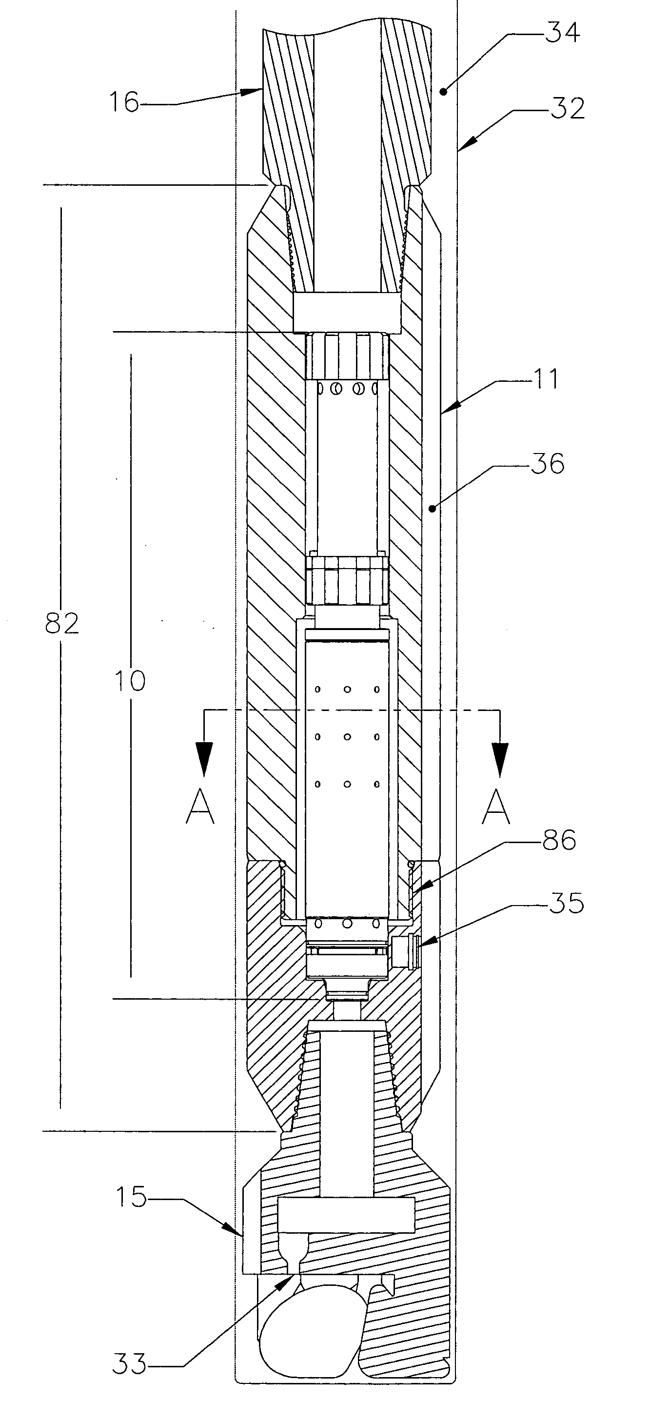
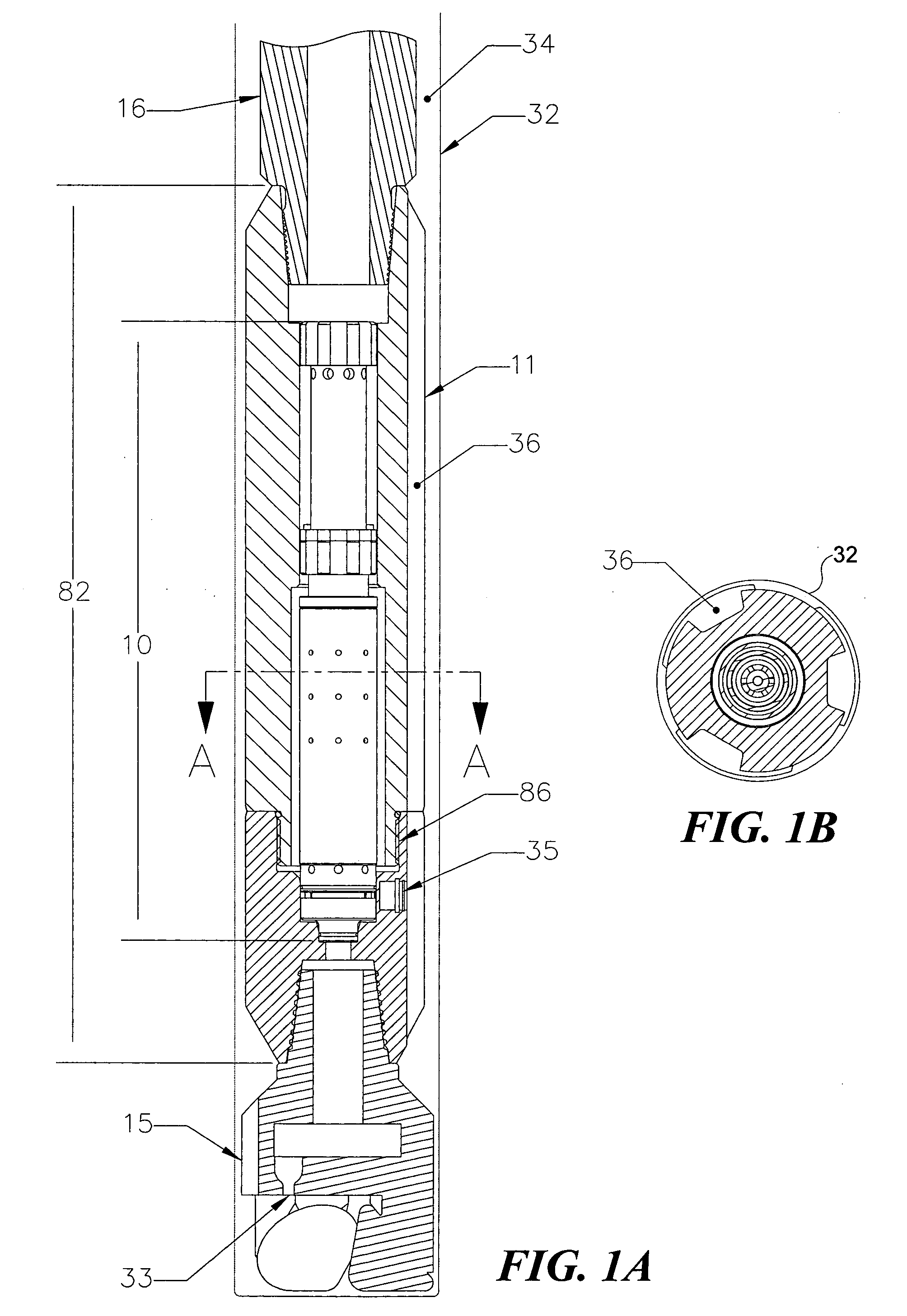
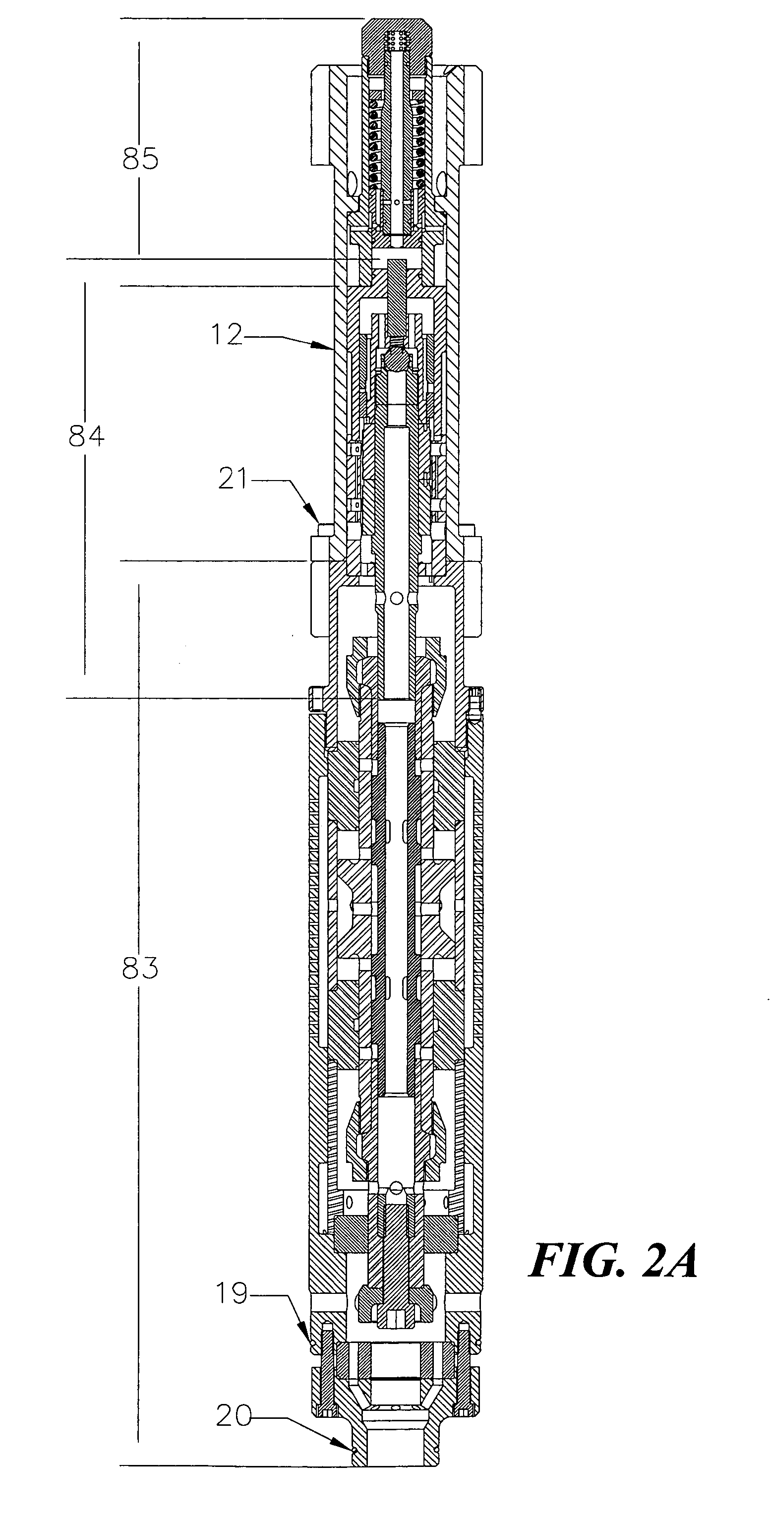
[0092] The present invention is both an improved hydraulic impulse generator and a frequency modulator that is usable with the hydraulic impulse generator to enable a broad range of frequencies to be generated during drilling, to achieve SWD with look ahead imaging. The text that follows first describes the improved hydraulic impulse generator and then describes the frequency modulator that can be used with the improved hydraulic impulse generator to achieve SWD. As noted above, an earlier design of a hydraulic impulse generator is described in commonly assigned U.S. Pat. No. 6;237,701, issued on May 29, 2001. The present invention corrects several problems with this earlier design, as discussed above under the Background of the Invention.

[0093]FIGS. 1A and 1B show the basic configuration of the improved hydraulic impulse generator, which is disposed at the bottom of a rotary drillstring 16. A hydraulic impulse generator 82 is part of a BHA of rotary drillstring 16, which is dispos...


PUM


Abstract

This invention discloses a valve that generates a hydraulic negative pressure pulse and a frequency modulator for the creation of a powerful, broadband swept impulse seismic signal at the drill bit during drilling operations. The signal can be received at monitoring points on the surface or underground locations using geophones. The time required for the seismic signal to travel from the source to the receiver directly and via reflections is used to calculate seismic velocity and other formation properties near the source and between the source and receiver. This information can be used for vertical seismic profiling of formations drilled, to check the location of the bit, or to detect the presence of abnormal pore pressure ahead of the bit. The hydraulic negative pressure pulse can also be used to enhance drilling and production of wells.

Description

GOVERNMENT RIGHTS [0001] This invention was made with U.S. Government support under Contract Nos. DE-FC26-97FT34367 and DE-FG03-00ER83111 awarded by the Department of Energy, and the government may have certain rights in this invention.FIELD OF THE INVENTION [0002] This invention generally relates to an apparatus and a method for interrupting the flow of a fluid within a borehole, and more specifically, to a valve and to a method for interrupting the flow of a incompressible liquid (e.g., drilling mud) through a drillstring in a borehole to generate a negative pressure pulse, and to applications for the negative pressure pulse that is thus generated. BACKGROUND OF THE INVENTION [0003] Numerous references describe tools located above a drill bit in a drillstring for periodically interrupting all or most of the drilling fluid flow to the bit. These tools fall into three general categories, based on their intended application. In the first category are hammer drills that periodically d...

Claims


Application Information

Patent Timeline
IPC IPC(8): E21B33/12E21B47/14E21B47/18G01V1/00G01V1/40G01V1/42
CPCE21B47/14G01V1/40G01V1/003E21B47/185E21B47/22Y10T137/2552
Inventor KOLLE, JACK J.MARVIN, MARK H.THEIMER, KENNETH J.
Owner WELLS FARGO BANK NAT ASSOC
Why Eureka
Try Eureka