
Fluorescent microarray analyzer

a microarray analyzer and fluorescence technology, applied in the direction of fluorescence/phosphorescence, luminescent dosimeters, optical radiation measurement, etc., can solve the problems of inability to accurately detect fluorescence signals, inability to exchange filters, and inability to obtain images in a long time.

Inactive Publication Date: 2005-08-18
KAIWOOD TECH
View PDF3 Cites 3 Cited by
  • Summary
  • Abstract
  • Description
  • Claims
  • Application Information

AI Technical Summary

Benefits of technology

"The present invention provides a fluorescent microarray analyzer that uses a spectrophotometer instead of a conventional biochip scanner device, resulting in accurate signals of fluorescence without the need for a filter. The analyzer allows for real-time analysis without scanning all samples on the biochip, saving time. The analyzer also eliminates errors occurring during the conversion of signals from the biochip to image data. The resulting signals of fluorescence are obtained by the spectrophotometer, which detects the fluorescence and produces signals that can be used to show the positions of DNA spots on the biochip. The analyzer provides a more accurate result of signals of fluorescence from samples and even allows for the use of more than two fluorophores on the same biochip."

Problems solved by technology

The conventional biochip is disadvantageous, since errors occur in the formation of the image data by processing the electrical signal and it takes much time to obtain the image.
In addition, problems of exchanging filters happens when two or more fluorophores are used on the same biochip.

Method used


Image

  • Fluorescent microarray analyzer
  • Fluorescent microarray analyzer
  • Fluorescent microarray analyzer

Examples


Embodiment Construction

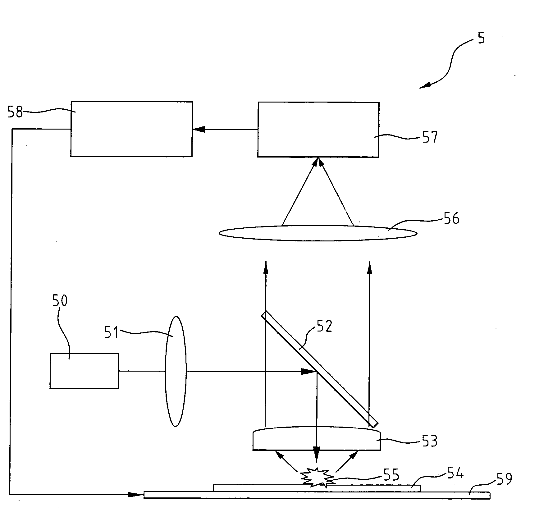
[0022] Preferred embodiments of the present invention will now be described in detail below with reference to the accompanying drawings. FIG. 3 is a schematic view showing an embodiment of a fluorescent microarray analyzer (5) of the present invention. The fluorescent microarray analyzer (5) comprises a light source (50) for emitting light beam; a beam splitter (52) for redirecting the light beam through a focusing lens (53), which focuses the reflected light beam onto a biochip (54) and exciting fluorescent targets on the biochip (54) to produce fluorescence (55); a focusing lens (56) for focusing the fluorescence on a spectrophotometer; a spectrophotometer (57) for detecting the fluorescence; and an output device (58) for receiving and displaying the signal detected by the spectrophotometer. A further focusing lens (51) may be set between the light source (50) and the beam splitter (52) to enhance the focusing effect.

[0023] A biochip is placed on a platform (59) first when analyz...


PUM

PropertyMeasurementUnit
central wavelengthaaaaaaaaaa

Abstract

A fluorescent microarray analyzer includes a light source for emitting a light beam, a light processing unit for focusing the light beam on the biochip and exciting fluorescent targets on the biochip to produce fluorescence, a focusing lens for focusing the fluorescence on a spectrophotometer, a spectrophotometer for detecting signal of the fluorescence, and an output device for selectively outputting / displaying the signal detected by the spectrophotometer. The resulting signal of the output device does not need to be converted into image data for analysis. For acquiring a more accurate result of detection of signal of fluorescence from the fluorescent targets, the photomultiplier tube of the conventional biochip scanner device is replaced with the spectrophotometer of fluorescent microarray analyzer of the present invention and the filter is removed. Without converting the signal into an image, no errors arise as what happened in process of converting an electrical signal into image data in the conventional biochip. Also, a real-time analysis of the signal proceeds while scanning samples on the biochip.

Description

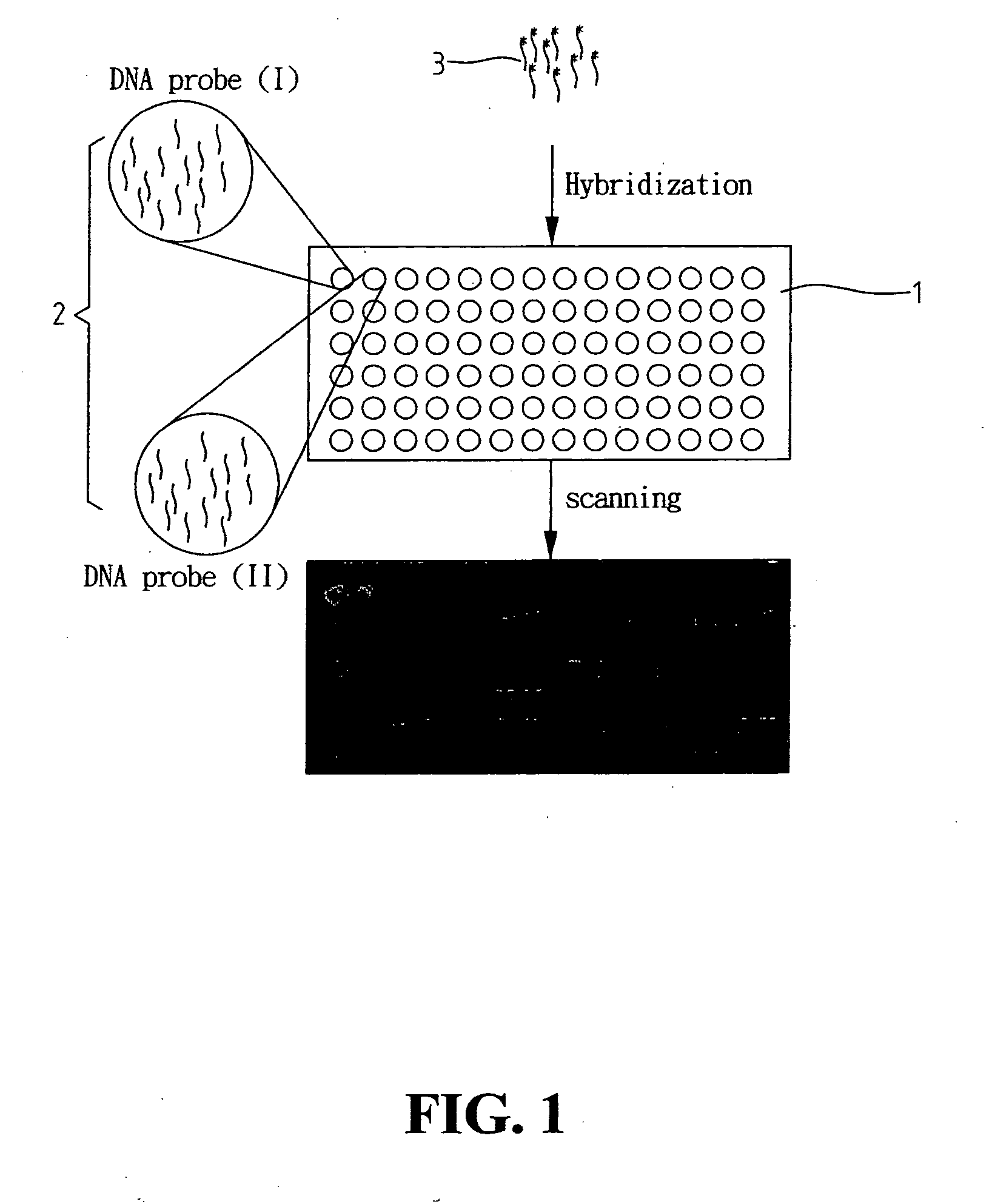
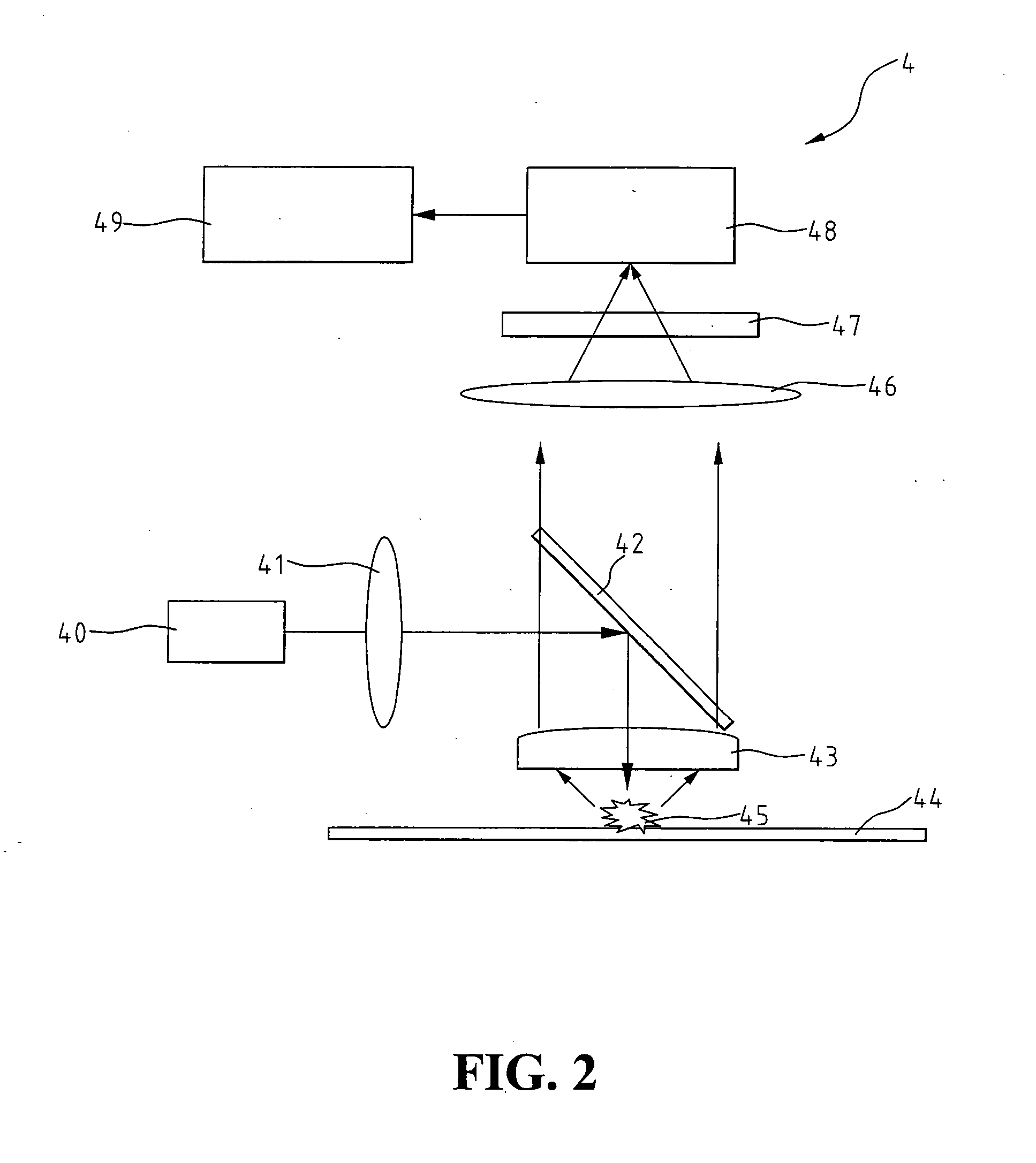
BACKGROUND OF THE INVENTION [0001] 1. Field of the Invention [0002] The present invention relates to a fluorescent microarray analyzer, particularly to a fluorescent microarray analyzer for detecting fluorescent signals emitting from a biochip by means of spectrum analysis. [0003] 2. The Prior Arts [0004] As “working draft” of the human sequence unraveled by the Human Genome Project published in Nature (15 Feb., 2001), simultaneously with a companion publication of the human sequence generated by Celera Genomics Corporation (Science, 16 Feb., 2001), understanding the physical functions and the mechanisms of human genes becomes the next important goal in the field. To accelerate the progress of the related research, high-throughput tools for efficient analysis are available. Biochip, results of mass of samples expressed on surface of a small solid carrier, is such a useful analytic tool. Biochip can be employed in gene expression, drug selection and disease diagnosis in both basic re...

Claims


Application Information

Patent Timeline
Patent Type & Authority Applications(United States)
IPC IPC(8): G01N21/64
CPCG01N2021/6417G01N21/6452
Inventor WANG, JIANN-HUACHEN, HUI JUWU, TZU-CHIANGCHUANG, CHIEN-HOCHUANG, TSUNG-KAI
Owner KAIWOOD TECH
Learn More