Grating element for filtering wavelengths < 100 nm

a technology of grating element and filtering wavelength, which is applied in the direction of diffraction grating, optics, instruments, etc., can solve the problems of high light loss, easy destruction, and difficult grating design of filters of this typ

Inactive Publication Date: 2005-08-18
CARL ZEISS SEMICON MFG
View PDF45 Cites 7 Cited by
  • Summary
  • Abstract
  • Description
  • Claims
  • Application Information

AI Technical Summary

Benefits of technology

[0039] In order to avoid too large of a thermal load on the physical diaphragm in the diaphragm plane or on following opti

Problems solved by technology

In illumination systems for wavelengths ≦100 nm, the problem exists that the light sources of illumination systems of this type emit radiation which may lead to undesired exposure of the light-sensitive object in the wafer plane of the projection exposure system and, in addition, optical components of the exposure systems, such as the multilayer mirror, are heated in this way.
Filters of this type have the disadvantage of high light losses.
Furthermore, they may be destroyed very easily through thermal stress.
For beam bundles at higher aperture, however, the grating design is more difficult, or greater aberrations are obtained.
If the requirement of separating the individual orders of diffraction is fulfilled, complicatedly constructed grating elements result,

Method used


Image

  • Grating element for filtering wavelengths &#x3c; 100 nm
  • Grating element for filtering wavelengths &#x3c; 100 nm
  • Grating element for filtering wavelengths &#x3c; 100 nm

Examples


Embodiment Construction

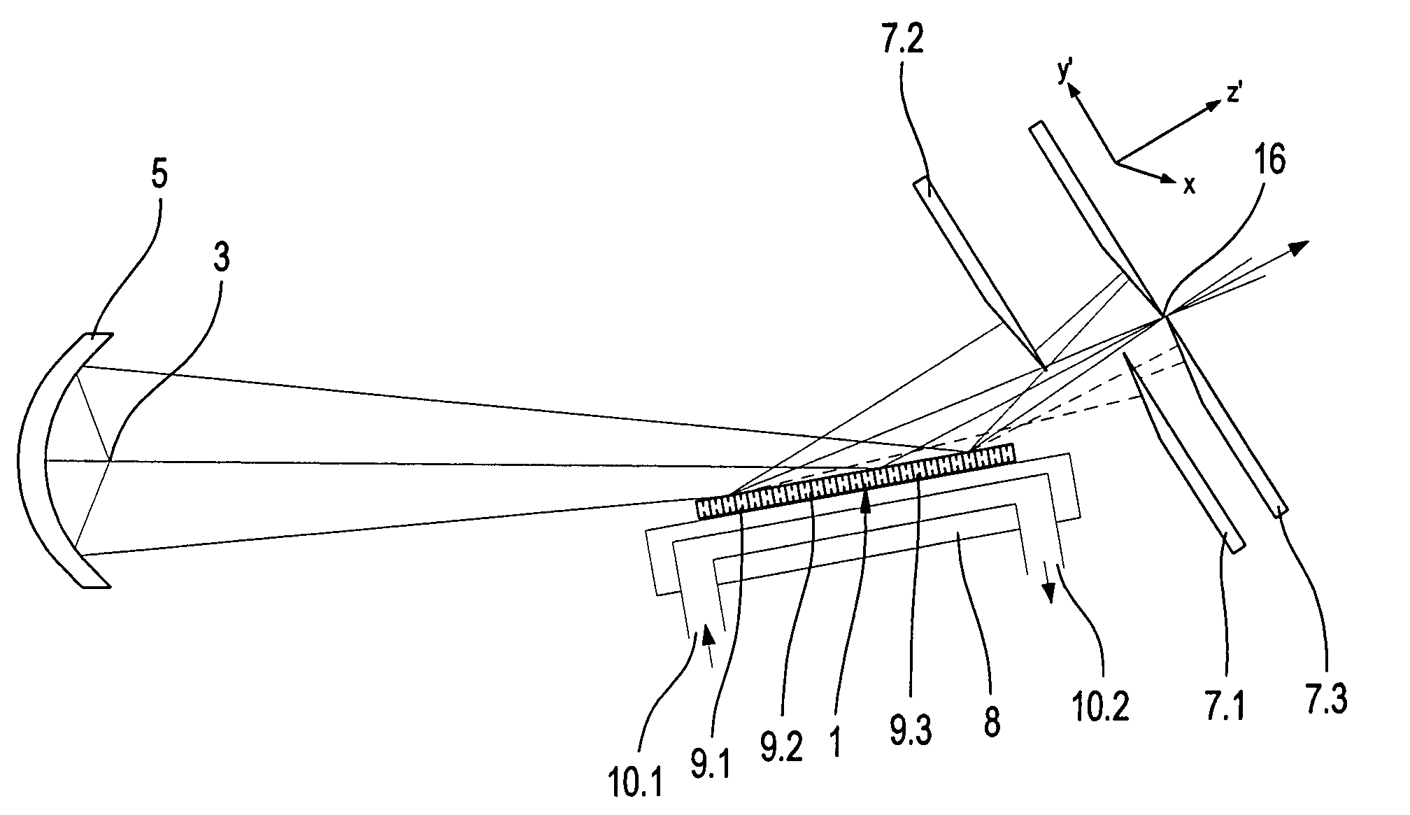
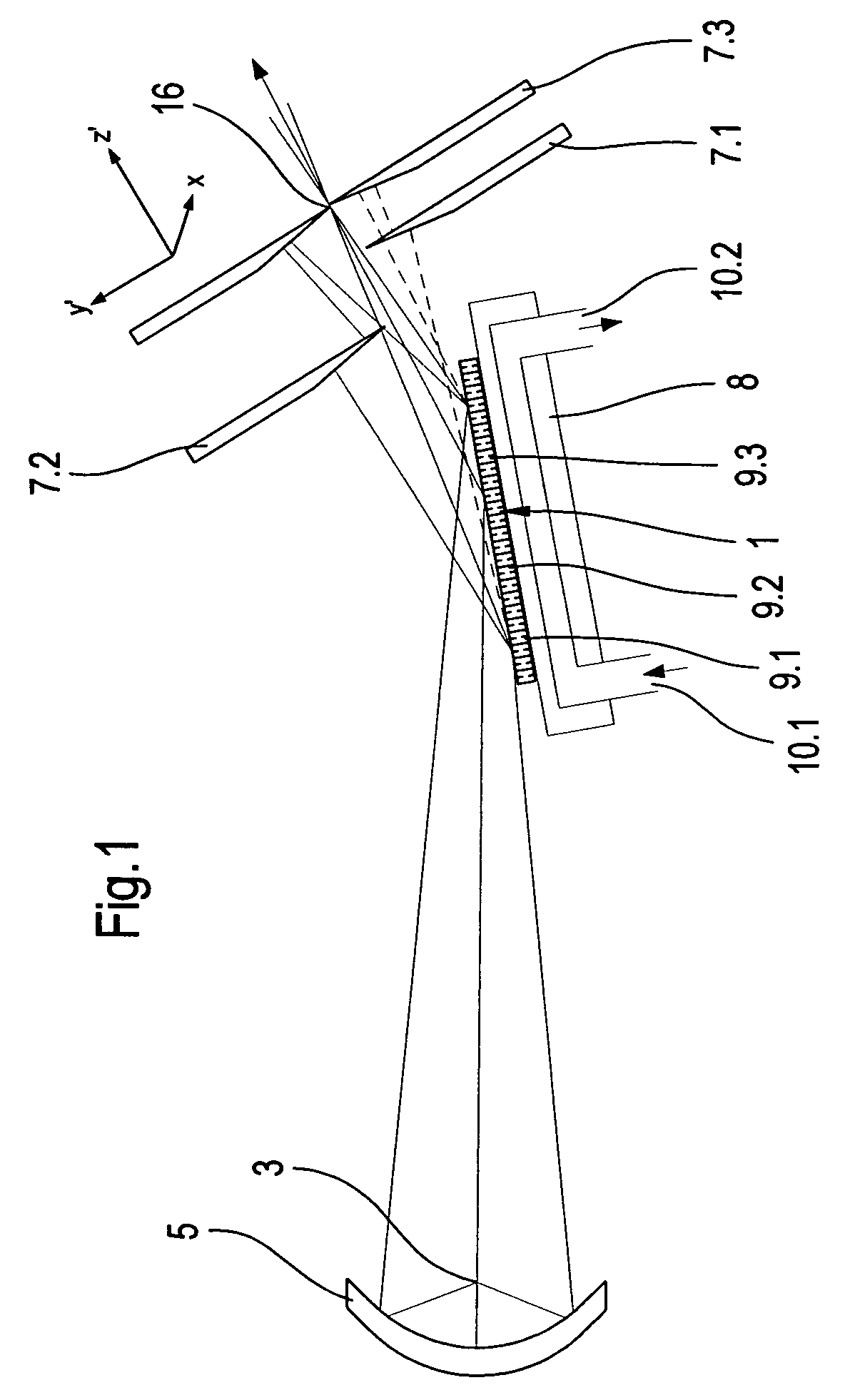
[0047]FIG. 1 shows a grating apparatus 1 having multiple individual gratings 9.1, 9.2, 9.3 in the beam path of an illumination system. The individual gratings 9.1, 9.2, 9.3 are positioned one behind another in the beam direction. The light of a light source 3 is collected by a collector unit, e.g., collector 5. In this example, the collector 5 is an ellipsoidal mirror which generates an image of the light source 3. The collimated light bundle having an aperture of approximately NA=0.1 downstream of the collector 5 is deflected via the grating apparatus 1 in grazing incidence in such a way that the intermediate image of the light source generated by the grating through diffraction in the +1st order of diffraction comes to lie at a focus 16 in or near the diaphragm plane of a physical diaphragm 7.3.

[0048] Undesired radiation may already be filtered out by multiple partial diaphragms 7.1, 7.2 positioned in front of the physical diaphragm 7.3, in order to reduce the thermal load on the...


PUM


Abstract

There is provided a grating apparatus for filtering wavelengths ≦100 nm. The grating apparatus includes multiple individual grating elements having grating lines. The individual grating elements are positioned one behind another on a curved support surface in relation to a plane spanned by the grating apparatus in a direction of beans of a light bundle that is incident on the grating apparatus.

Description

CROSS-REFERENCE TO RELATED APPLICATIONS [0001] The present application is a continuation of International Application No. PCT / EP03 / 02419, filed Mar. 10, 2003, which claims priority of German Patent Application No. 102 12 691.7, filed Mar. 21, 2002. The content of these applications is herein incorporated by reference.BACKGROUND OF THE INVENTION [0002] 1. Field of the Invention [0003] The present invention relates to a grating element for filtering wavelengths ≦100 nm, having multiple individual grating elements, the individual grating elements having grating lines resulting in a grating periodicity. [0004] 2. Description of the Related Art [0005] In order to be able to reduce the structure widths for electronic components even further, particularly in the submicron range, it is necessary to reduce the wavelength of the light used for microlithography. The use of light having wavelengths less than 100 nm, e. g., lithography using soft x-rays, i.e., EUV lithography, for example, is co...

Claims


Application Information

Patent Timeline
IPC IPC(8): G01J3/18G02B5/18G02B27/00
CPCG02B5/1838G02B27/4244G02B27/0043G02B5/1861
Inventor HEIDEMANN, KLAUSOSTERRIED, KARLFRID
Owner CARL ZEISS SEMICON MFG
Why Eureka
Try Eureka