Communication apparatus and communication method

a communication apparatus and communication method technology, applied in multiplex communication, frequency-division multiplex, wireless commuication services, etc., can solve the problems of limited transmission area as compared, difficulty in multiplexing a plurality of channels, and readiness to undergo influence, so as to achieve stable communication

Inactive Publication Date: 2005-08-18
PANASONIC INTELLECTUAL PROPERTY CORP OF AMERICA
View PDF11 Cites 37 Cited by
  • Summary
  • Abstract
  • Description
  • Claims
  • Application Information

AI Technical Summary

Benefits of technology

[0013] A communication apparatus according to the present invention, solving the foregoing problem, is allowed for suited communication by assigning transmission subcarriers, depending upon communication information substance (significance, control information or not), information capacity and communication quality required. This enables communications highly flexible and immune to noises.
[0014] Meanwhile, a communication apparatus comprises: a transmission modulator for impulse-modulating transmission data and generating subcarriers; a carrier control section for controlling the subcarriers for use in communication depending upon information amount, significance and communication propagation condition; and an antenna section for radiating the subcarrier signals. This can select subcarriers suited for transmission information and propagation environment, hence allowing for communications highly flexible and immune to noises.
[0015] Meanwhile, a communication apparatus according to the invention further comprises a reception modulator for detecting reception data and examining a reception power on each subcarrier, to notify to the subcarrier control section a permission / non-permission to use the subcarrier, depending upon the reception power examined by the reception demodulator. This can dynamically change the subcarriers for use in changing the communication environment, hence making possible to secure stable communication quality.
[0032] Meanwhile, a communication apparatus according to the invention is characterized in that the antenna section comprises a plurality of antenna elements. Consequently, because the antenna elements are superior in narrower band characteristic in respect of radiation characteristic and mechanical form, size reduction and performance improvement are facilitated.
[0047] Meanwhile, a communication method according to the present invention further comprises a step of measuring a reception power on every subcarrier of a received known signal at a start of communication; and a step of selecting the subcarrier having the measured reception power equal to or greater than a predetermined value, as a subcarrier usable in communication. This can detect a subcarrier with which transmission data is not easy to propagate, hence allowing for communications using only a subcarrier suited for communication.
[0048] As described above, the present invention allows for a quality, stable communication immune to interfering waves.

Problems solved by technology

Impulse modulation scheme involves the problem of being ready to undergo interference from other systems and hence become instable during communication because of its occupation over a broadband frequency.
Meanwhile, because of band occupation, there is a difficulty in multiplexing a plurality of channels.
However, in the configuration of U.S. Pat. No. 5,677,927, because communication is by a broad use of band on the impulse modulation scheme, there is a difficulty in avoiding against the system that issues high output signals in a part of the band, resulting in readiness to undergo influence.
Namely, concerning the higher-frequency subcarrier, there is limitation in the area for transmission as compared to the lower-frequency subcarrier.
Free space propagation loss: loss increases with increasing frequency.
Consequently, the communication system using impulse modulation scheme has the problem of the above conspicuous setbacks, as compared to the communication system in the prior art having a carrier interval of approximately several MHz to several tens MHz.

Method used


Image

  • Communication apparatus and communication method
  • Communication apparatus and communication method
  • Communication apparatus and communication method

Examples


embodiment 1

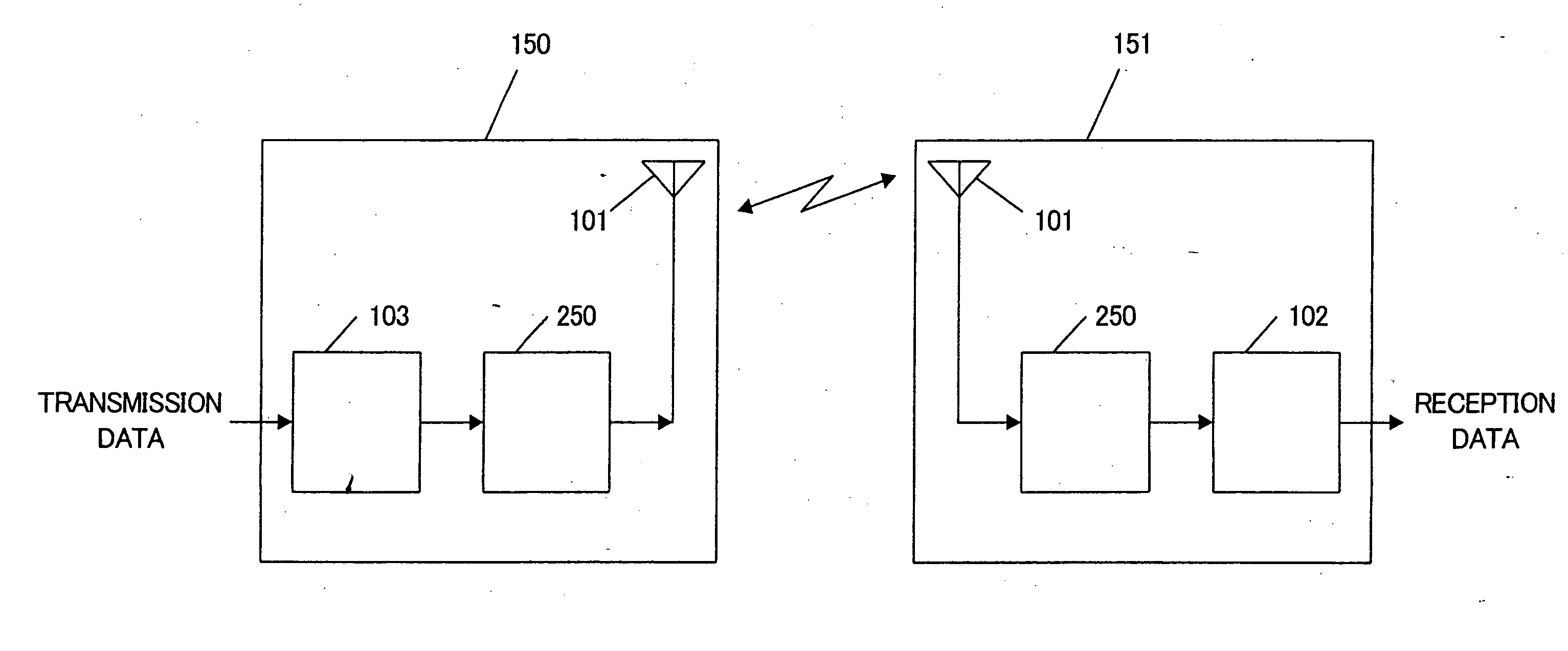
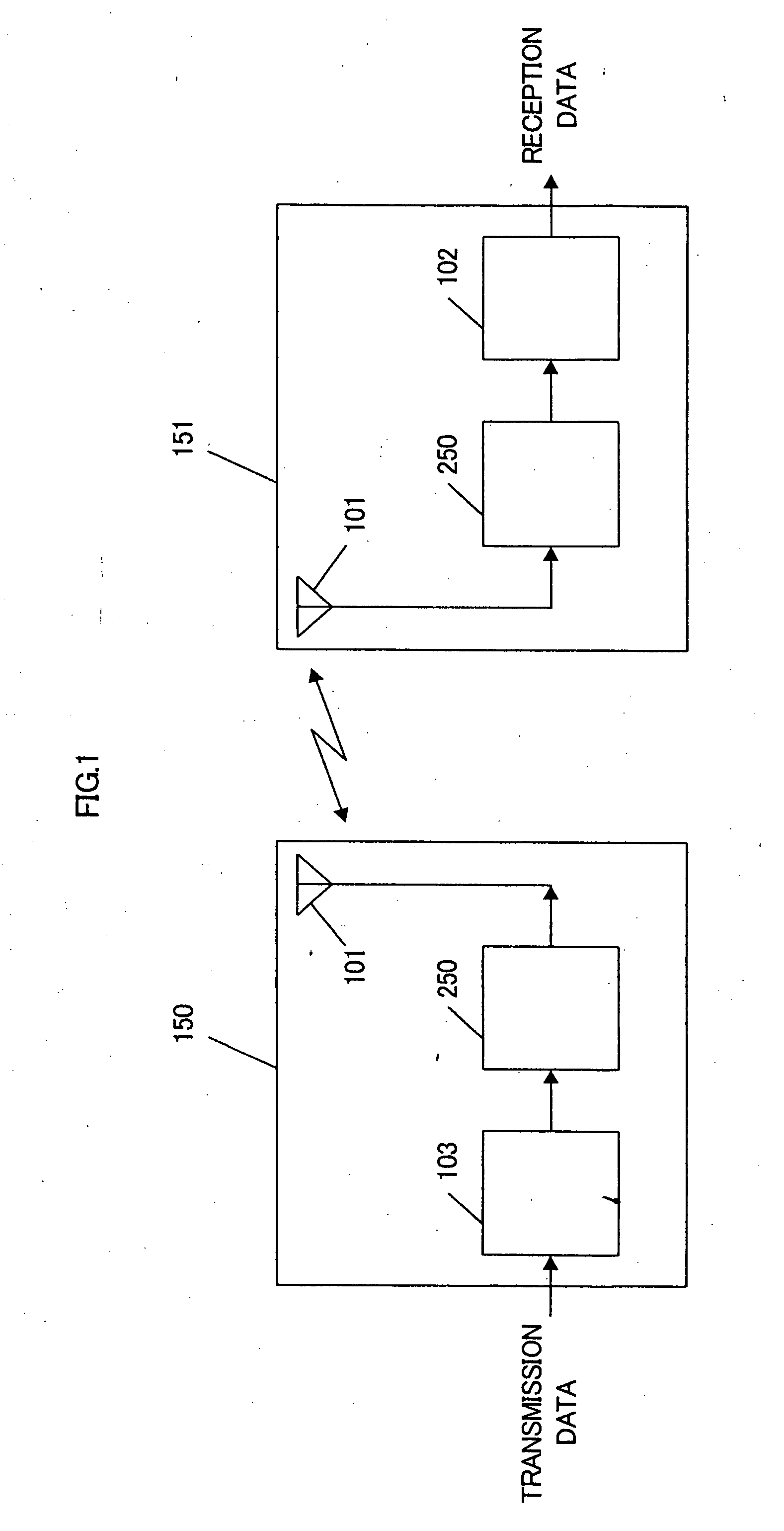
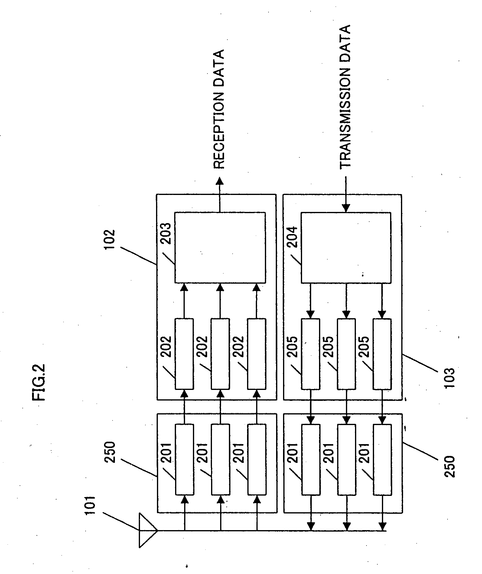
[0095] Using the figures, explanation is made on the invention (particularly in demodulation) that an impulse signal is divided into two or more bandwidths (subcarriers), the signals of which are to be used in implementing communication. FIG. 1 is a diagram showing a communication system using the conventional impulse modulation signal, wherein 150 represents a transmitter apparatus and 151 a receiver apparatus. The transmitter apparatus 150 comprises an antenna section 101 and a transmission modulator 102 while the receiver apparatus 151 comprises an antenna section 101 and a reception demodulator 103. FIG. 2 is a diagram explaining in detail the transmitter apparatus 150 and the receiver apparatus 151 shown in FIG. 1, thus configuring a transceiver apparatus as a combination of the transmitter apparatus 150 and the receiver apparatus 151 for the sake of convenience. The blocks corresponding to FIG. 1 are attached with the same references, hence to describe herein the different poi...

embodiment 2

[0112] With the use of figures, explanation is made on the invention that the impulse modulation signal is divided into two or more bands (subcarriers) to thereby multiplex a plurality of channels of impulse modulation communications by use of the subcarrier signals. FIG. 40 is a diagram showing an arrangement of a transmission apparatus 150 and reception apparatus 151 according to the present embodiment. In FIG. 40, there is a difference from that of embodiment 1 in that the transmission modulator 103 has further a channel control section 4001 while the reception demodulator 102 has further the channel control section 4001. The channel control section 4001 selects and controls the subcarriers to be used on a channel-by-channel basis.

[0113] There is shown in FIG. 15 a correspondence between a communication and a subcarrier. As shown in FIG. 15, it is assumed that channel 1 is under communication by use of subcarriers f1, f3, f4, f6 while channel 2 is under communication by use of s...

embodiment 3

[0123] Explanation is made on the invention that the impulse modulation scheme is divided into two or more bands (subcarriers) so that communication is effected by spreading codes to the subcarrier.

[0124] Embodiment 1 was explained to implement communication to attach the same symbol on all the subcarriers assigned to one channel. However, in the case a plurality of subcarriers are assigned to one channel, there is no need to send the same symbols to all the subcarriers assigned. FIG. 17 shows a relationship between a subcarrier and a code. The example shown in FIG. 17 shows a state that subcarrier f1-f7 are assigned to a certain channel. Meanwhile, this figure represents that symbol set ss1 is used in transmission for subcarriers f1, f3, f6 while symbol set ss2 is used in transmission for subcarriers f2, f4, f5, f7.

[0125] In the below, explained is a communication system for transmission of binary data. This system includes at least two symbols (s1, s2). Provided that the relatio...


PUM


Abstract

There are included a transmission modulator (103) for impulse-modulating the data to be transmitted, thereby producing a subcarrier; a subcarrier control section for controlling the subcarrier to be utilized for communication, depending on the amount and significance of information and on the propagation condition of communication; and an antenna section (101) for radiating the subcarrier signal. This structure allows selection of a subcarrier suitable for information to be transmitted and for propagation environment, and hence allows a communication to be performed which exhibits a high flexibility and a high noise immunity. Thus, there can be provided a communication apparatus that can perform a high-quality, high-stability communication exhibiting an improved interfering immunity and that performs a flexible impulse communication.

Description

TECHNICAL FIELD [0001] The present invention is a technique for use in digital radio communication and, more particularly, relates to a technique for in impulse communication. BACKGROUND ART [0002] Digital radio communication now occupies the important position in the field of communication by virtue of the technological development thereof. In an attempt to pursue higher speed of communication, study has being put forward toward communication using impulse modulation scheme. Impulse modulation scheme involves the problem of being ready to undergo interference from other systems and hence become instable during communication because of its occupation over a broadband frequency. Meanwhile, because of band occupation, there is a difficulty in multiplexing a plurality of channels. [0003] However, as means for solving this, there are those as described in U.S. Pat. No. 5,677,927, for example. FIG. 44 shows the conventional communication apparatus described in U.S. Pat. No. 5,677,927. [0...

Claims


Application Information

Patent Timeline
Patent Type & Authority Applications(United States)
IPC IPC(8): H04J1/00H04B1/713H04B1/7176H04B7/26H04J13/00H04L27/26H04W72/04
CPCH04B1/692H04B1/71632H04L27/2614H04L27/2602H04B1/719
Inventor ORIHASHI, MASAYUKIMURAKAMI, YUTAKA
Owner PANASONIC INTELLECTUAL PROPERTY CORP OF AMERICA
Why Eureka
Try Eureka