
System and method for power pump performance monitoring and analysis

a power pump and performance monitoring technology, applied in the field of system and method for power pump performance monitoring and analysis, can solve the problems of pump operating characteristics having a deleterious effect on pump performance, loss of volumetric efficiency, wear and tear, etc., and achieve the effect of convenient utilization

Inactive Publication Date: 2005-08-18
MHWIRTH
View PDF7 Cites 96 Cited by
  • Summary
  • Abstract
  • Description
  • Claims
  • Application Information

AI Technical Summary

Benefits of technology

[0011] The performance analysis system of the present invention further includes an easily utilized sensor for determining the positions of the pump plungers or pistons for one complete revolution of the pump eccentric or crankshaft. An optical switch including a beam interruption, mountable on a pump crosshead extension part, for example, is easily provided, requires no intrusion into the power end of the pump, and is operable to provide pump piston or plunger position determination and pump speed.

Problems solved by technology

However, a reciprocating piston power pump is inherently a hydraulic pressure pulse generator producing hydraulic imposed forces that cause wear and tear on various pump components, including but not limited to piping connected to the pump, the pump cylinder block or so-called fluid end, inlet and discharge valves, including actuating springs, and seal components, including piston or plunger seals.
Pump operating characteristics can have a deleterious affect on pump performance.
For example, delayed valve closing and sealing can result in loss of volumetric efficiency, and indicate a need for increased pulsation dampener sizing requirements.
For example, delayed valve response also causes a higher pump chamber pressure than normal.
Higher pump chamber pressures may cause overloads on pump mechanical components, including the pump crankshaft or eccentric and its bearings, speed reduction gearing, the pump drive shaft and the pump prime mover.
Moreover, increased fluid acceleration induced pressure “spikes” in the pump suction and discharge flowstreams can be deleterious.
Still further, piston or plunger seal or packing leaking can result in increased delay of pump discharge valve opening with increased hydraulic flow and acceleration induced hydraulic forces imposed on the pump and its discharge piping.

Method used


Image

  • System and method for power pump performance monitoring and analysis
  • System and method for power pump performance monitoring and analysis
  • System and method for power pump performance monitoring and analysis

Examples


Embodiment Construction

[0031] In the description which follows like elements are marked throughout the specification and drawing with the same reference numerals, respectively. Certain features may be shown in somewhat schematic form in the interest of clarity and conciseness.

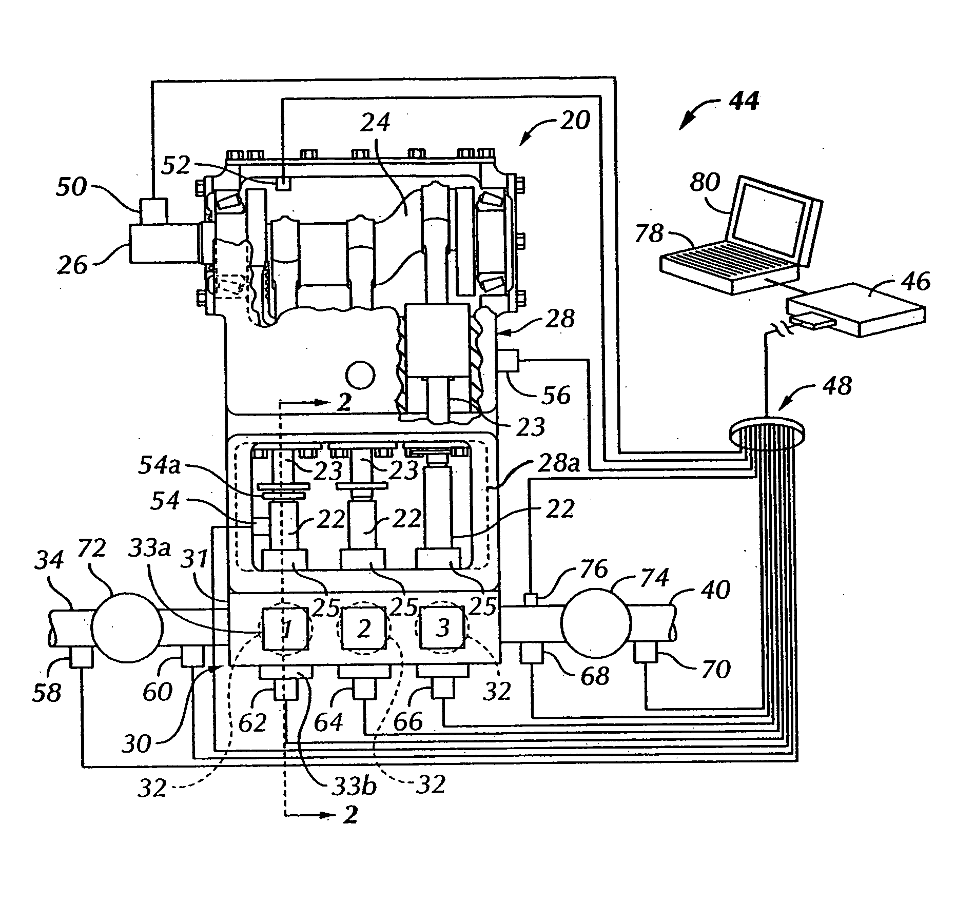
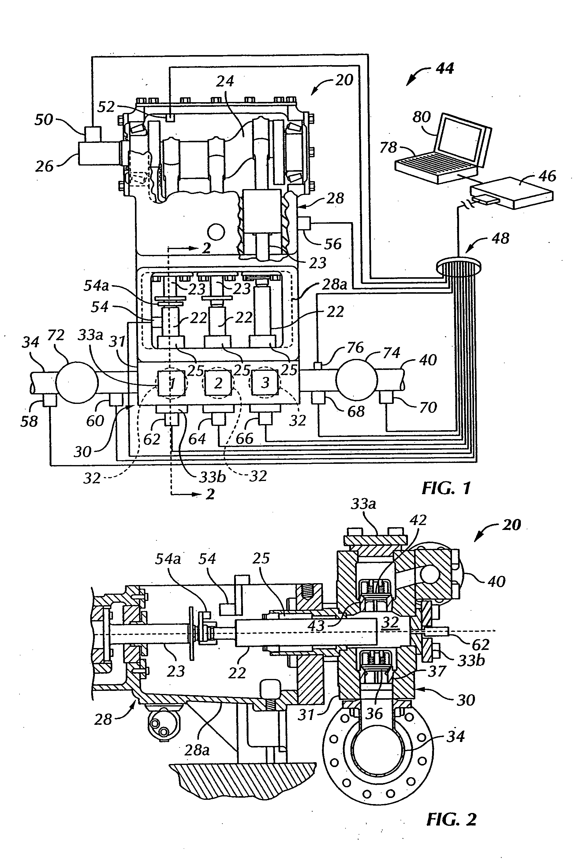
[0032] Referring to FIG. 1, there is illustrated in somewhat schematic form, a reciprocating plunger or piston power pump, generally designated by the numeral 20. The pump 20 may be one of a type well-known and commercially available and is exemplary in that the pump shown is a so-called triplex plunger pump, that is the pump is configured to reciprocate three spaced apart plungers or pistons 22, which are connected by suitable connecting rod and crosshead mechanisms, as shown, to a rotatable crankshaft or eccentric 24. Crankshaft or eccentric 24 includes a rotatable input shaft portion 26 adapted to be operably connected to a suitable prime mover, not shown, such as an internal combustion engine or electric motor, for example. Cran...


PUM


Abstract

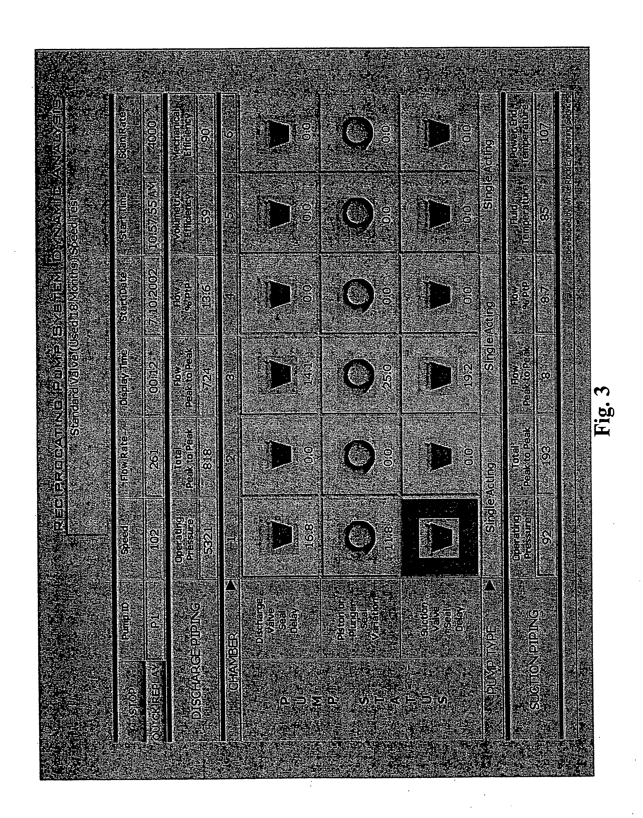
A power pump performance analysis system includes a signal processor connected to pressure sensors for sensing pressures in the cylinder chambers and inlet and discharge piping of a single or multi-cylinder pump. Pump speed and piston position are determined by a crankshaft position sensor. Pump vibration, fluid temperatures, and power input may also be measured by sensors connected to the processor. Performance analyses, including determination of pump volumetric efficiency, mechanical efficiency, suction and discharge valve sealing delay, valve and piston seal leakage, flow induced pressure variations, acceleration induced pressure detection, hydraulic resonance detection and pulsation dampener performance may be measured and selected parameters displayed on a visual display connected to the processor directly or via a network.

Description

BACKGROUND [0001] Reciprocating piston positive displacement pumps, often called power pumps, are ubiquitous, highly developed machines used in myriad applications. However, a reciprocating piston power pump is inherently a hydraulic pressure pulse generator producing hydraulic imposed forces that cause wear and tear on various pump components, including but not limited to piping connected to the pump, the pump cylinder block or so-called fluid end, inlet and discharge valves, including actuating springs, and seal components, including piston or plunger seals. [0002] There has been a longstanding need to provide improved performance analysis for reciprocating piston power pumps, in particular, to determine if deteriorations in pump performance are occurring, to analyze the source of decreased performance and to further provide an analysis which may be used to schedule replacing certain so-called expendable parts of the pump prior to possible catastrophic failure. [0003] Pump operati...

Claims


Application Information

Patent Timeline
IPC IPC(8): F04B39/00F04B49/00F04B51/00G01M7/00G06F9/06
CPCF04B51/00
Inventor MILLER, J. DAVIS
Owner MHWIRTH
Learn More