Check patentability & draft patents in minutes with Patsnap Eureka AI!

Wireless terminals

a wireless terminal and terminal technology, applied in the direction of simultaneous aerial operations, substation equipment, antennas, etc., can solve the problems of unsatisfactory undesired complications and unavailability of volume, and achieve the effect of simplifying the architecture of wireless terminals

Inactive Publication Date: 2005-08-18
NXP BV
View PDF2 Cites 13 Cited by
  • Summary
  • Abstract
  • Description
  • Claims
  • Application Information

AI Technical Summary

Benefits of technology

[0006] An object of the present invention is to simplify the architecture of a wireless terminal.

Problems solved by technology

To achieve such a bandwidth from a PIFA for example requires a considerable volume, there being a direct relationship between the bandwidth of a patch antenna and its volume, but such a volume is not readily available with the current trends towards small handsets.
The provision of a diplexer although enabling the cited antenna arrangement to work satisfactorily represents an undesired complication.

Method used


Image

  • Wireless terminals
  • Wireless terminals
  • Wireless terminals

Examples


Embodiment Construction

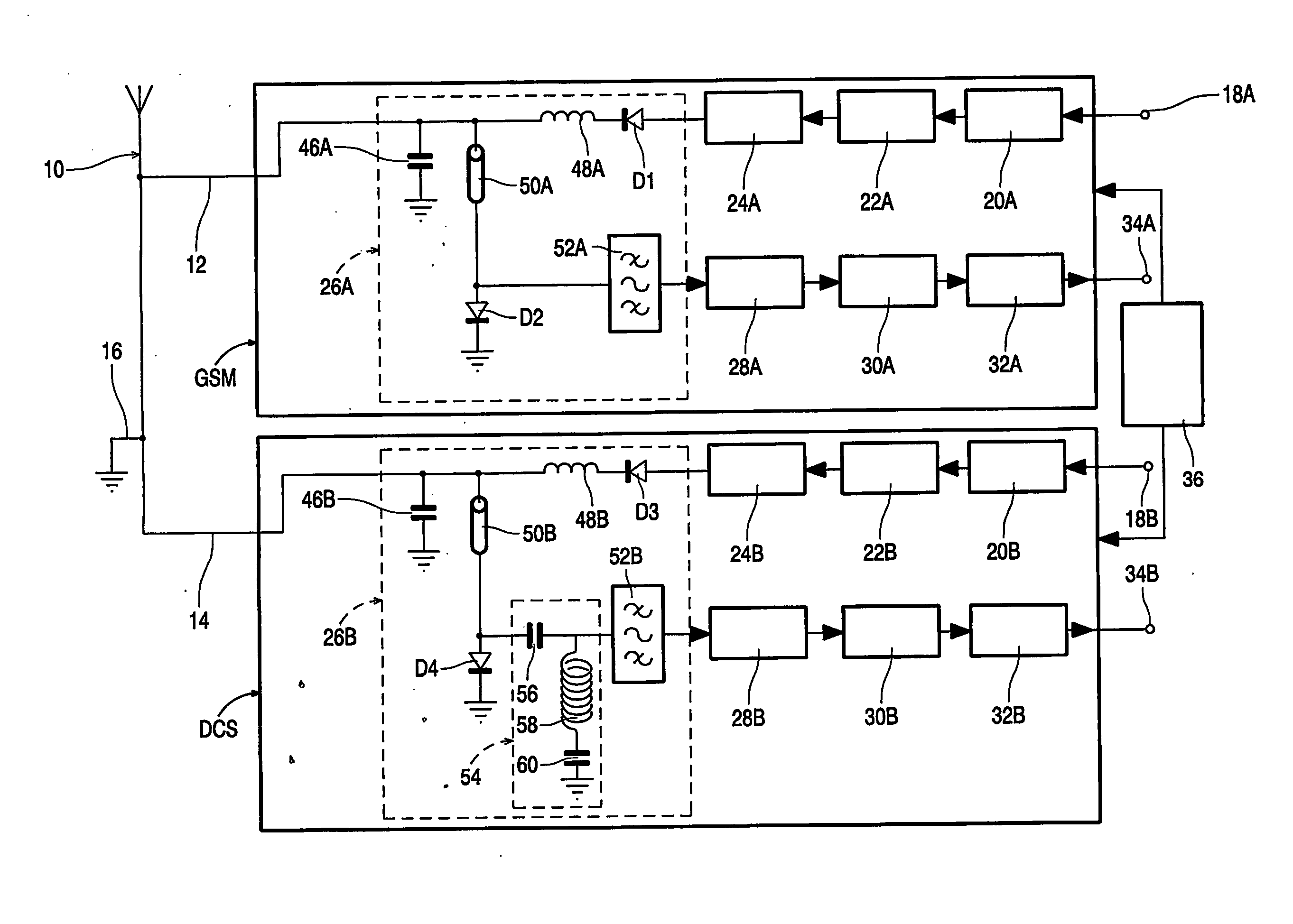
[0030] Referring to FIG. 1, the wireless terminal comprises a PIFA antenna 10 having feeds 12 and 14 to which are connected a GSM transceiver which operates in a frequency band of 880 to 960 MHz and a DCS transceiver which operates in the frequency band 1710 to 1880 MHz, respectively. A ground pin 16 is provided between the feeds 12, 14 as shown in FIG. 2 to be described later. As the architectures of the GSM and the DCS transceivers are generally the same the corresponding stages will be referenced with the suffices A and B respectively and in the interests of brevity only the GSM transceiver will be described. The transmitter section of the GSM transceiver comprises a signal input terminal 18A coupled to an input signal processing stage 20A. The stage 20A is coupled to a modulator 22A which provides a modulated signal to a transmitter stage 24A which includes a frequency up-converter, power amplifier and any relevant filters. A common coupling stage 26A couples the transmitter sta...


PUM


Abstract

A wireless terminal having a dual band antenna arrangement which comprises a planar inverted-F antenna (10) having a first (12) for signals in a first, lower frequency band, for example the GSM band, a second feed (14) for signals in a second, higher frequency band, for example the DCS band, and a ground pin (16). A first coupling stage (26A) couples the transmit and receive paths of a first transceiver (GSM) to the first feed and a second coupling stage (26B) couples the transmit and receive paths of a second transceiver (DCS) to the second feed. Each of the first and second coupling stages comprise a quarter wavelength transmission line (50A, 50B) having a first end coupled to the respective transmit signal path and a second end coupled by band pass filter (52A, 52B) to the respective receive signal path. A first PIN diode (D1, D3) couples a transmit signal path to the first end of the respective quarter wavelength transmission line and to the respective feed (t2, t4) and a second PIN diode (D2, D4) couples the second end of the respective quarter wavelength transmission line to ground. In operation when transmitting in one of the bands, the first and second PIN diodes of the relevant coupling stage are switched-on, whilst the PIN diodes in the other coupling stage are off and when in a receiving mode all the PIN diodes are off. The signal being received by one of the transceivers is reflected by the band pass filter in the coupling stage of the other transceiver.

Description

TECHNICAL FIELD [0001] The present invention relates to wireless terminal, for example a cellular telephone, having a dual-band antenna arrangement comprising a substantially planar patch antenna, and to a module incorporating such an arrangement. In the present specification, the term dual-band antenna relates to an antenna which functions satisfactorily in two (or more) separate frequency bands but not in the unused spectrum between the bands. BACKGROUND ART [0002] Wireless terminals, such as mobile phone handsets, typically incorporate either an external antenna, such as a normal mode helix or meander line antenna, or an internal antenna, such as a Planar Inverted-F Antenna (PIFA) or similar. [0003] Such antennas are small (relative to a wavelength) and therefore, owing to the fundamental limits of small antennas, narrowband. However, cellular radio communication systems typically have a fractional bandwidth of 10% or more. To achieve such a bandwidth from a PIFA for example requ...

Claims


Application Information

Patent Timeline
Patent Type & Authority Applications(United States)
IPC IPC(8): H01Q5/10H01P1/15H01Q13/08H03H7/46H04B1/44
CPCH03H7/46H04B1/44H01Q5/00
Inventor BOYLE, KEVIN R.
Owner NXP BV
Features
  • R&D
  • Intellectual Property
  • Life Sciences
  • Materials
  • Tech Scout
  • Unparalleled Data Quality
  • Higher Quality Content
  • 60% Fewer Hallucinations
Learn More