Eureka AIR delivers breakthrough ideas for toughest innovation challenges, trusted by R&D personnel around the world.

Gas monitor using electrochemical cell and method of operating

Active Publication Date: 2005-08-25
HONEYWELL ANALYTICS AG
View PDF3 Cites 2 Cited by
  • Summary
  • Abstract
  • Description
  • Claims
  • Application Information

AI Technical Summary

Benefits of technology

[0010] The primary purpose of the present invention is to enhance the safety of users and personnel within the area being monitored. The present system accomplishes this objective by issuing a signal, referred to as an Initial Warning, when a detected concentration C1 of the gas being monitored at the first flow rate equals or exceeds the Alert level. At this stage, because of the possible errors mentioned above, it is not known for certain whether the sensed signal is an accurate representative of concentration or, perhaps, due to a system fault or other signal error of the type mentioned. Thus, the present invention seeks to confirm or deny that the sensed signal causing the Initial Warning is in fact caused by an undesired concentration of the gas being monitored or by an error or fault. One immediate benefit provided by the invention is a higher level of operator confidence in the issuance of an Alarm following an Initial Warning.
[0014] The controller has stored in memory, table information specifying desired flow rates and concentration data for particular EC cells and associated gases. Certain EC cells are known to be more accurate when operating with gases flowing at specific rates as persons skilled in the art know. In operation, the system may detect the presence in the apparatus of certain, specific EC cells, as by mechanical configuration or keying or electrical identification, alerting the controller to set the flow rate for optimum sensing capability for the particular cell and gas being monitored, according to the stored table look-up data. This enables the same monitoring system to work with different EC cells, and is particularly advantageous to manufacturers of gas monitoring systems who then need not customize the monitoring system for individual EC cells or for particular gases.
[0019] The present invention also contemplates that the flow rate of the gas being monitored may be changed on a periodic basis (i.e. cycled repetitively between F1 and F2), permitting the verification process to be further expedited by reducing the total lapsed time for the first and second sensor measurements. Periodic cycling of the flow rates may also improve the accuracy of the sensor readings at the two flow rates. For example, a baseline can be established for the “Alert” level at the first flow rate F1 which may improve accuracy and reduce the time for verification.
[0020] The quick-reaction verification processes of the present invention are advantageous because conventional measuring systems typically record detected signal levels and such systems are under control of a data processor so that computation of signal levels, polarities and change rates is rapid, straightforward and requires no additional hardware.
[0021] Of significance, however, are the following factors: (1) fault verifications incorporating a quick-reaction technique will reduce the total time for an Initial Warning measurement and confirmation to a matter of a few seconds, as compared with the ninety seconds or more which would typically be required for two successive EC cell signal measurements, changing of flow rates and corresponding computations of gas concentration levels; and (2) the second reading at a different flow rate confirms that the EC cell is measuring a gas response, not sensor background signal.

Problems solved by technology

At this stage, because of the possible errors mentioned above, it is not known for certain whether the sensed signal is an accurate representative of concentration or, perhaps, due to a system fault or other signal error of the type mentioned.
However, if the concentration detected at the first flow rate is not confirmed at the second flow rate, notification is given of the disparity for further investigation, short of any immediate remedial action or Alarm which might cause system shut down.

Method used


Image

  • Gas monitor using electrochemical cell and method of operating
  • Gas monitor using electrochemical cell and method of operating
  • Gas monitor using electrochemical cell and method of operating

Examples


Embodiment Construction

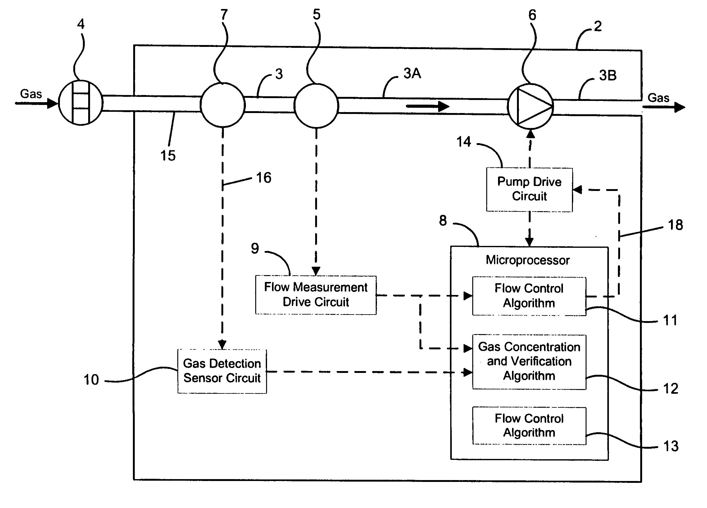
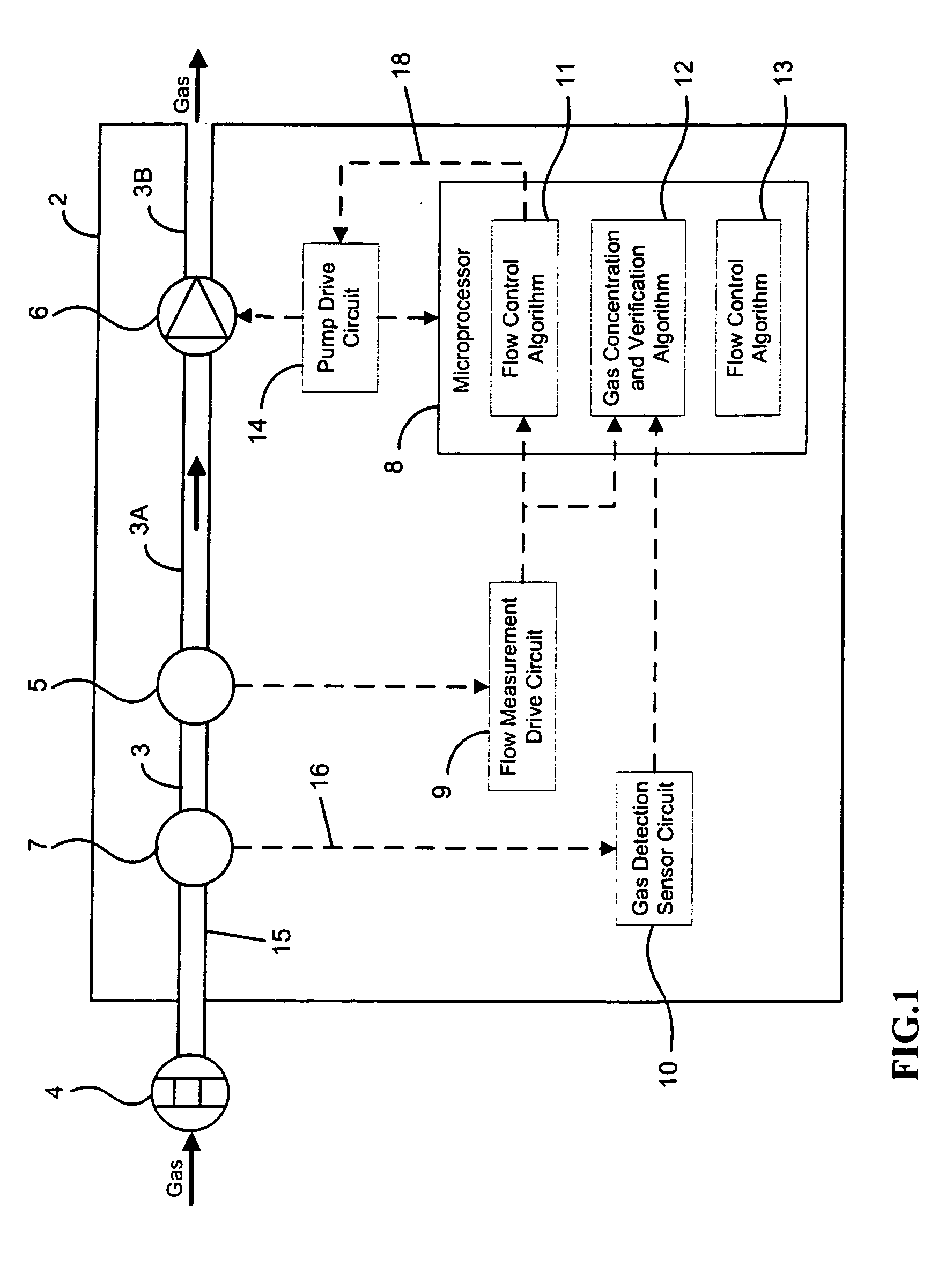
[0030] Referring first to FIG. 1, gas is drawn from a volume being monitored through a filter 4 to a gas detection or monitoring instrument 2, which may be referred to as an aspirator. The gas being monitored is fed from the filter 4 through an inlet passage 15 to an electrochemical cell 7 (“sensor”). The gas is then routed through a passage 3 to a flow measuring device (flow meter) 5. The gas is then routed through a passage 3A to a gas pump 6 which returns the gas to the system being monitored through an outlet passage 3B. Pump 6 may preferably be a conventional diaphragm pump, having a controllable flow rate as described further below.

[0031] The EC cell 7 generates an electrical signal which is coupled along lead 16 to a conventional gas detection sensor circuit 10 which detects the signal of the EC cell 7 and processes it to a digital electrical signal representative of the output of the EC cell 7. This digital signal, in turn, is fed to a processor-based controller 8 which is ...


PUM


Abstract

A method and apparatus for gas detection uses a sensor such as an electrochemical (EC) cell and includes a feedback control loop to control a pump to establish a first predetermined gas flow rate to the EC cell. The concentration of the gas at the first predetermined flow rate is measured. If the detected concentration exceeds a predetermined Alert value at the first flow rate an Initial Warning without remedial action is generated, and, the system then changes the gas flow rate before an Alarm is indicated. An Alarm is signaled only if the system verifies the first measurement. Preferably the first flow rate is set to optimize the measurement accuracy of the EC cell being used, and the second flow rate is lower than the first. Verification of an Alarm at the first flow rate may be conducted quickly by a quick-reaction process. The controller may periodically cycle the flow rates between the first and second rates for better accuracy and faster verification times.

Description

RELATED APPLICATIONS [0001] This is a Non-Provisional Application of co-pending, co-owned provisional application No. 60 / 537,087, for “Gas Monitor Using Electrochemical Cell and Method of Operating”, filed on Jan. 15, 2004 and co-pending, co-owned provisional application No. 60 / 567,140, for “Gas Monitor Using Electrochemical Cell and Method of Operating”, filed on Apr. 30, 2004.FIELD OF THE INVENTION [0002] The present invention relates to monitors using Electrochemical (EC) cells for detecting and measuring the concentration of gases, typically toxic or other undesirable gases, or liquids. BACKGROUND OF THE INVENTION [0003] Electrochemical cells are used to detect the presence and measure the concentration of gases or other fluids. Different cells are known to be responsive to different, specific gases or other fluid / sensor combinations where the response of the sensor is affected by the presence of a diffusion layer within the fluid, as with electrochemical cells. The response cha...

Claims


Application Information

Patent Timeline
IPC IPC(8): G01N7/00G01N33/00
CPCG01N33/0063
Inventor TIWET, JOHN A.STONE, CARY S.GORNY, RICHARD A.CHAPPLES, JOHNROBINS, IAN
Owner HONEYWELL ANALYTICS AG
Why Eureka
Eureka Blog
Learn More