Patterned thin-film deposition using collimating heated masked assembly

a technology of collimating heated masks and patterned thin films, which is applied in the direction of vacuum evaporation coatings, solid-state devices, coatings, etc., can solve the problems of large area contact masks, large contact masks, and fine-sized features that are prone to warping and distortion

Inactive Publication Date: 2005-08-25
OPTOELECTRONICS SYST
View PDF12 Cites 76 Cited by
  • Summary
  • Abstract
  • Description
  • Claims
  • Application Information

AI Technical Summary

Benefits of technology

[0024] (iii) a built-in shutter mechanism ...

Problems solved by technology

Contact masks typically exhibit the following limitations: i) fine-sized features are prone to clogging due to material deposition along the edges of the openings; ii) in the contact mode, mask removal can cause scratching of the deposited pattern; iii) large area contact masks are prone to warping and distortion; iv) circular stand-alone pattern elements cannot be supported (such as the letter “P”, “O”, etc .
However, increased radiation adversely affects the quality of the deposited films as the spacing between subs...

Method used


Image

  • Patterned thin-film deposition using collimating heated masked assembly
  • Patterned thin-film deposition using collimating heated masked assembly
  • Patterned thin-film deposition using collimating heated masked assembly

Examples


Embodiment Construction

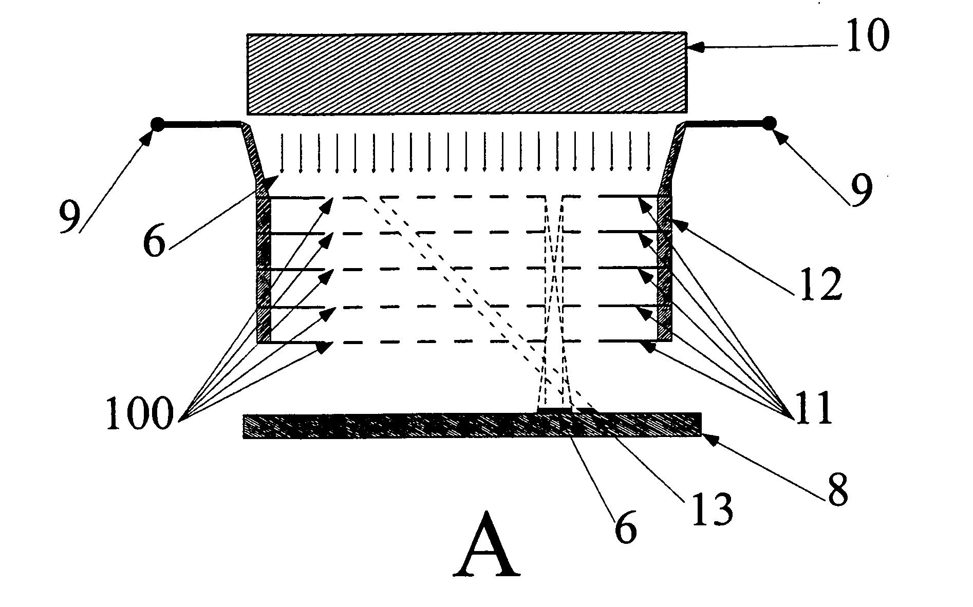
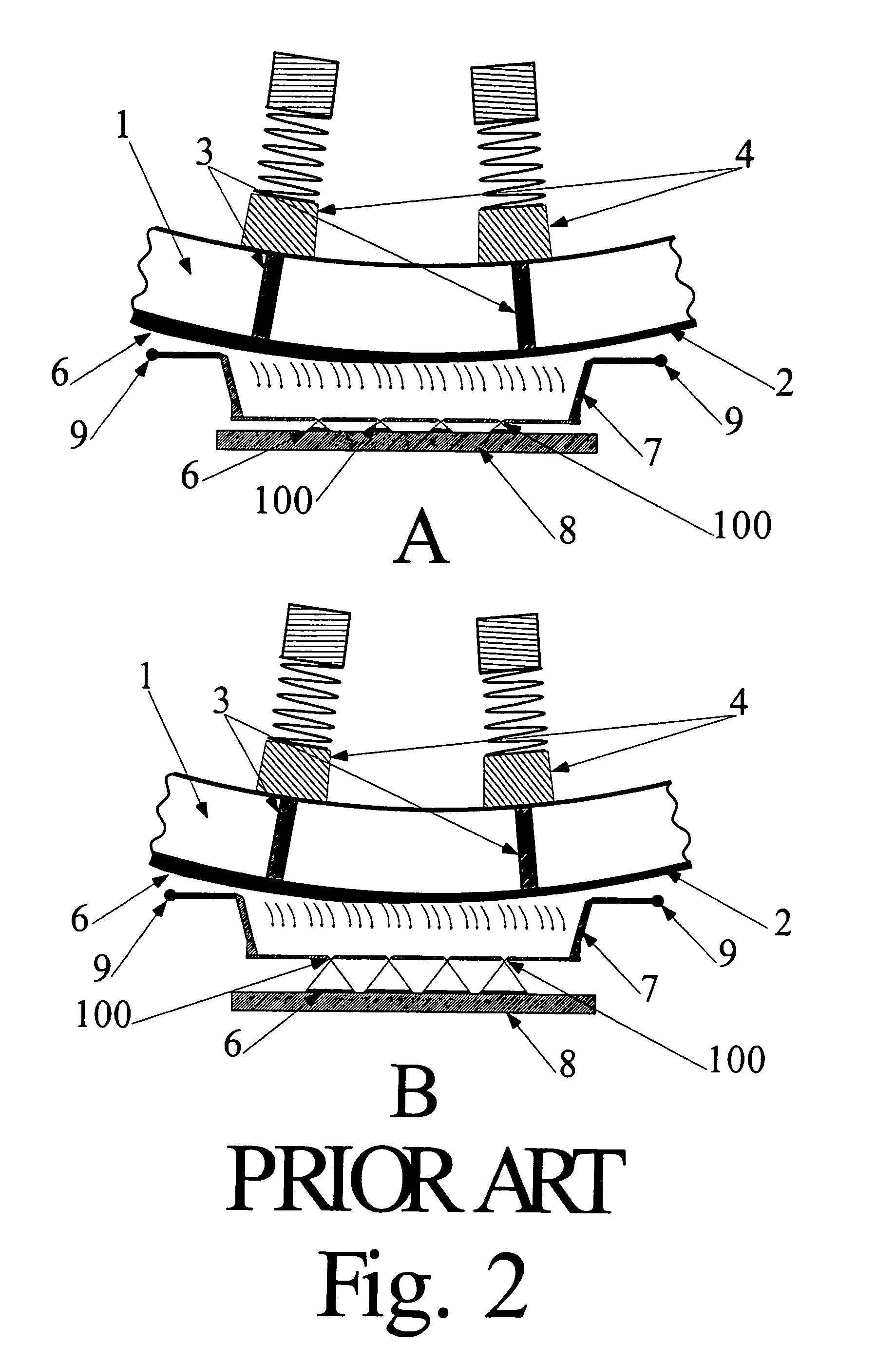
[0049] The present invention utilizes a multilevel heated collimating shadow mask assembly that resolves the problems discussed hereinbefore. FIGS. 3A and 3B show two embodiments of such an assembly, constructed of a multiplicity of individual shadow masks 11, stacked equidistantly (FIG. 3A) or aperiodically (FIG. 3B). In both cases, the apertures or openings 100 in all of the individual shadow masks are vertically aligned with respect to each other, allowing free passage of the vapor stream from the generic evaporating heating element 10 to the substrate 8. Moreover, each of the masks 11 is fabricated from an electrically resistive material. Passing current through the contacts 9 and 12 resistively heats this mask assembly to prevent the clogging of the mask openings 100 caused by deposition of the evaporant 6 onto the masks 11. The heated collimating mask assembly provides the necessary collimation of the vapor stream material 6 for deposition of high definition patterns of materi...


PUM

PropertyMeasurementUnit
Temperatureaaaaaaaaaa
Electrical resistivityaaaaaaaaaa

Abstract

Scanning localized evaporation and deposition of an evaporant on a substrate utilizes a mask assembly comprised of a series of mask elements with openings thereon and spaced apart in a stack. The openings are aligned so as to direct the evaporant therethrough onto the substrate. The mask elements are heated and the stack may include a movable shutter element to block openings in adjacent mask elements. The evaporant streams are usually vertical but some may be oblique to the substrate, and they may be of different materials.

Description

[0001] This application is a division of application Ser. No. 10 / 252,884, filed Sep. 24, 2002, pending.BACKGROUND OF THE INVENTION [0002] The present invention is directed to a method for improving the deposition of patterned thin films using a scanning localized evaporation methodology (SLEM) incorporating a collimating mask assembly for producing multilayered electronic and photonic devices, such as transistors, sublimable organic light-emitting diodes (OLEDs), photonic band gap structures, and integrated circuits and systems. [0003] The growth of ultra-thin organic films currently involves predominantly the use of high vacuum,[1, 2] Langmuir-Blodgett film deposition,[3-5] or self-assembled monolayers.[6-11] Typically, producing high resolution patterns in these films requires the use of lithographic techniques that enable the selective removal of portions of the deposited layers.[12, 13] Lately, soft stamping[14-18] and ink-jet printing[19-22] have permitted direct patterned depo...

Claims


Application Information

Patent Timeline
IPC IPC(8): C23C14/04C23C14/22H01L51/00H01L51/40
CPCC23C14/044H01L51/001C23C14/22H10K71/164
Inventor GRANTHAM, DANIEL HARRISONPHELY-BOBIN, THOMAS SAMUELPAPADIMITRAKOPOULOS, FOTIOSJAIN, FAQUIR C.
Owner OPTOELECTRONICS SYST
Why Eureka
Try Eureka