Injection molding of polymers by microwave heating

a technology of injection molding and microwave heating, which is applied in the direction of manufacturing tools, electric/magnetic/electromagnetic heating, food shaping, etc., can solve the problems of increased material and handling costs, inability to mold by microwave, so as to reduce the injection pressure and reduce the ratio between flow length and wall thickness. , the effect of improving the ratio between flow length and wall thickness

Inactive Publication Date: 2005-08-25
AKOPYAN RAZMIK L
View PDF65 Cites 19 Cited by
  • Summary
  • Abstract
  • Description
  • Claims
  • Application Information

AI Technical Summary

Benefits of technology

[0027] When the microwave oven is incorporated into the injection assembly, some measures must be taken to prevent the leakage of microwave radiation through the gaps between hydraulic piston and the wall of the microwave oven and the drive for any carousel mechanism associated therewith. Such measures include providing the gaps as small as practical and, if necessary, utilizing a quarter wavelength choke. The same measures may be taken to prevent the leakage of microwave radiation through a hole in the oven for the nozzle.
[0028] The microwave injection molding system disclosed herein may be utilized for molding relatively massive parts of relatively thick cross-section. Molding such relatively thick parts may require utilization of injection-compression molding techniques (ICM). ICM is a system in which the molten polymer is injected into a slightly opened mold. After completion of injection or during the final phase of injection, the moving platen of the mold is pressed or compressed toward the stationary platen, creating the compressive stroke. In this case, the moving mold half exerts pressure directly against the solidifying plastic resin. By using ICM, the injection pressure can be reduced and the ratio between flow length and wall thickness also improves. During the holding pressure phase, the material is not subject to any shear stress, so the molded products exhibit little orientation and little tendency to warp.
[0029] In order to provide rapid heating and cooling of the injection mold cavity, the mold members include mold plates or mold cavity plates defining the interior mold cavity and having interior channels for receiving heating and cooling elements or medium. The mold plates are thermally insulated from the rest of the mold assembly by a layer of rigid thermal insulation. The mass of these plates is significantly smaller than the total mass of the mold. Insulating the mold cavity plates from the rest of the mold assembly allows for relatively rapid preheating of the mold cavity plates to the desired temperature prior to injection of the mold material and rapid cooling upon completion of the injection of molten polymer.

Problems solved by technology

Nevertheless, in spite of significant advantages, microwave compression molding has drawbacks.
Also grinding pellets to a fine powder results in increased material and handling costs.
Although the use of pellets avoids the additional cost associated with grinding the pellets into fine powder, compression molding of pellets can result in finished product showing visible borders at the interfaces between molten granules.
In addition, if the microwave compression molding process is not performed with adequate compression or compaction of the pellets, the resulting product can also have undesirable voids or pores.
Because of their molecular structure, plastics have low thermal conductivities; thus it is difficult to rapidly transmit heat through the polymers by conduction.
Due to the low thermal conductivity of plastics, the ratio of the volume of the material injected out of the plasticizing unit to the heating surface area of the plasticizing unit per cycle is relatively small and therefore inefficient.
However, increasing the shot capacity by accumulation of molten plastic in the rear zone of plasticizing unit may cause plastic degradation due to prolonged heating and is not desirable.
As discussed above, for many polymers the dielectric losses are not sufficient to permit raising of the polymer's temperature from room or ambient temperatures to its melting or softening temperature through microwave heating.
Therefore, microwave processing of such polymers is generally considered impractical, especially for polymers containing glass fillers.
However, none of these known prior art microwave drying systems are adapted for use in melting or plasticizing the plastic material as part of an injection molding system.

Method used


Image

  • Injection molding of polymers by microwave heating
  • Injection molding of polymers by microwave heating
  • Injection molding of polymers by microwave heating

Examples


Embodiment Construction

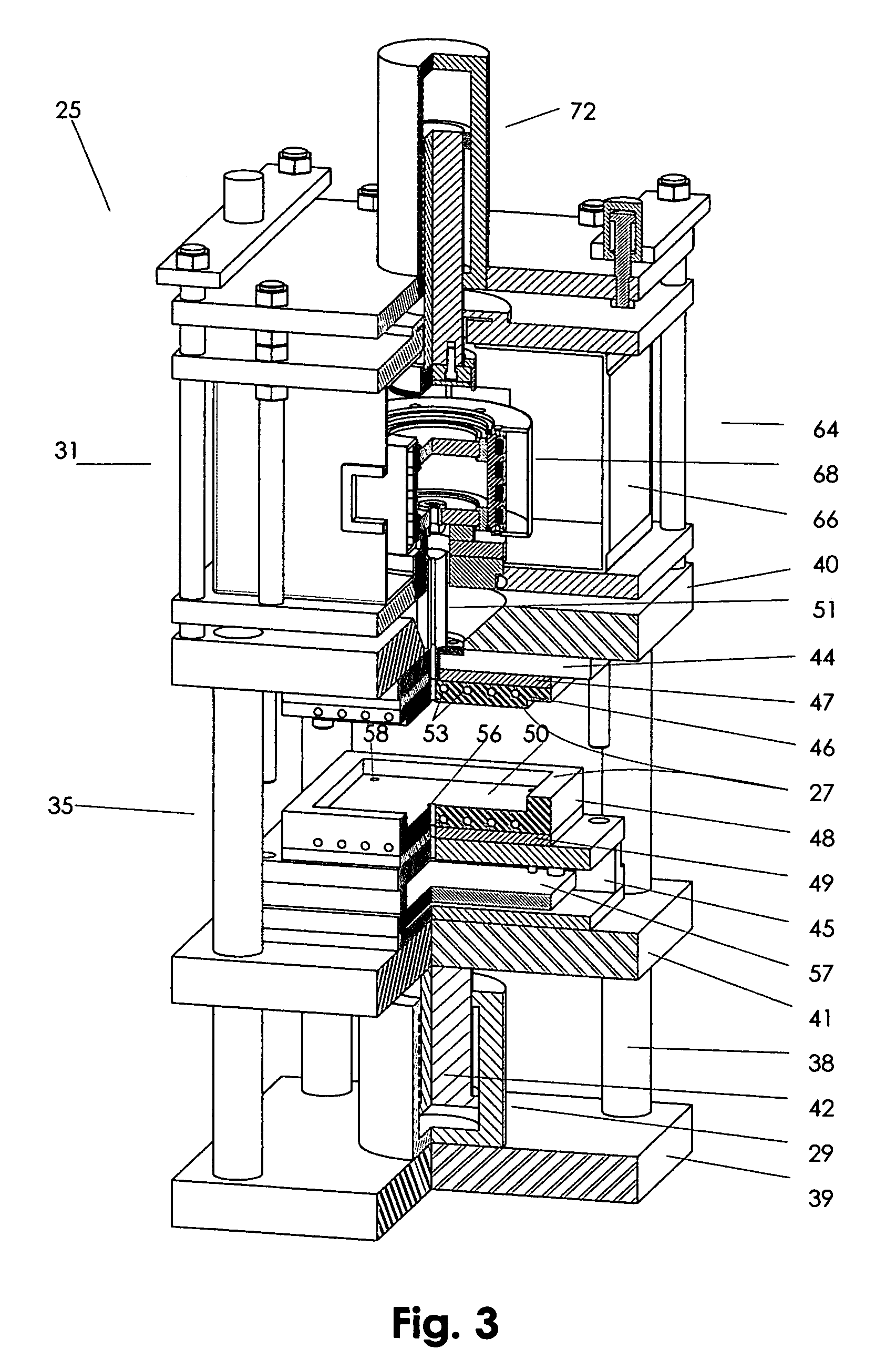
[0044] Referring to the drawings in more detail, one embodiment of a microwave injection molding system 25 of the present invention is shown in FIG. 3. The injection molding system 25 comprises an injection mold 27, a mold clamping press 29 for opening and closing the mold 27, a plasticizing unit 31 in which plastic granules are received and heated to their melting point and an injection assembly 33 for ejecting molten plastic out of the plasticizing unit 31 and into the mold 27. In the embodiment shown in FIG. 3, the foregoing components are all mounted or adapted to be supported on a frame 35.

[0045] The injection mold 27 and mold clamping press 29 are generally of conventional design. Referring to FIG. 3, the mold 27 shown for illustrative purposes, is shaped for molding rectangular shaped parts. It is to be understood that the mold may be designed or shaped to mold parts of various shapes and dimensions. The mold press 29 comprises a first set of tie bars 38 which are fixedly co...


PUM

PropertyMeasurementUnit
compression pressureaaaaaaaaaa
heat deflection temperatureaaaaaaaaaa
critical temperatureaaaaaaaaaa

Abstract

Injection molding machine utilizes microwave heating. A microwave oven adapted to receive a microwave absorbent plasticizing vessel is utilized with or incorporated into an injection molding system to form a plasticizing unit for heating polymer granules to an injection temperature and injection of the melt into the cavity of the injection mold. The polymer granules may be preheated by conventional heating systems to a temperature at which the granules become microwave absorbent before heating to the injection temperature in the microwave oven. The injection molding machine also contains a hydraulic actuator for injection of the melt. The ceramic materials forming the plasticizing vessel are selected to provide equal heating rates of mold members and relatively uniform heating of polymer to desired injection temperature.

Description

CROSS-REFERENCE TO RELATED APPLICATION [0001] This U.S. Patent application is a continuation in part of and claims the benefit under 35 U.S.C. 120 of the filing date of U.S. patent application Ser. No.'s 10 / 157,324 filed May 29, 2002, Ser. No. 10 / 435,315 filed May 9, 2003 and U.S. patent application Ser. No. 10 / 868,574 filed Jun. 15, 2004.BACKGROUND OF THE INVENTION [0002] This invention relates to the injection molding of engineered thermoplastics including fiber reinforced plastics which perform at extremely high temperatures and stresses. The processes and apparatus disclosed herein may also be utilized for injection molding of thermosets. [0003] In previously filed patent applications, including application Ser. No. 10 / 868,574 entitled Microwave Molding of Polymers, Publication No. US-2004-0222554-A1, and application Ser. No. 10 / 435,315 entitled Microwave Molding of Polymers, Publication No. US-2003-0224028-A1, I disclosed methods for creating compression molds for use in the co...

Claims


Application Information

Patent Timeline
Patent Type & Authority Applications(United States)
IPC IPC(8): B29C33/38B29C35/08B29C45/17B29C45/53B29C45/74
CPCB29C33/3828B29C33/3835B29C35/0805B29C2035/0855B29C45/53B29C45/74B29C45/1761
Inventor AKOPYAN, RAZMIK
Owner AKOPYAN RAZMIK L
Why Eureka
Try Eureka