Apparatus and method for minimizing power loss associated with dead time

a technology of dead time and apparatus, applied in the field of power supplies, can solve the problems of significant dead time loss, high power loss penalty for significant overlap, and additional 27 mw power loss per nanosecond of dead time, and achieve the effect of minimizing power loss, cost effective and convenient, and minimizing overall converter power loss

Active Publication Date: 2005-08-25
INFINEON TECH AMERICAS CORP
View PDF21 Cites 45 Cited by
  • Summary
  • Abstract
  • Description
  • Claims
  • Application Information

AI Technical Summary

Benefits of technology

[0018] It is an object of the present invention to provide an improved method and apparatus for minimizing power losses associated with dead time in a power converter circuit. According to the invention, dead time is varied in such a manner so as to minimize overall converter power losses. Several means are ...

Problems solved by technology

The power loss penalty for significant overlap is extremely high compared to the additional conduction losses occurring during dead time.
Still, dead time losses are significant, especially as converter operating frequency is increased.
With the above conditions, this translates into an additional 27 mW power loss per nanosecond of dead time.
Two switching edges per cycle of 20 ns dead time each results in an additional 1.088 watts of loss in the synchronous switch, a 20% increase in losses for that component.
Using a Schottky diode in ...

Method used


Image

  • Apparatus and method for minimizing power loss associated with dead time
  • Apparatus and method for minimizing power loss associated with dead time
  • Apparatus and method for minimizing power loss associated with dead time

Examples


Embodiment Construction

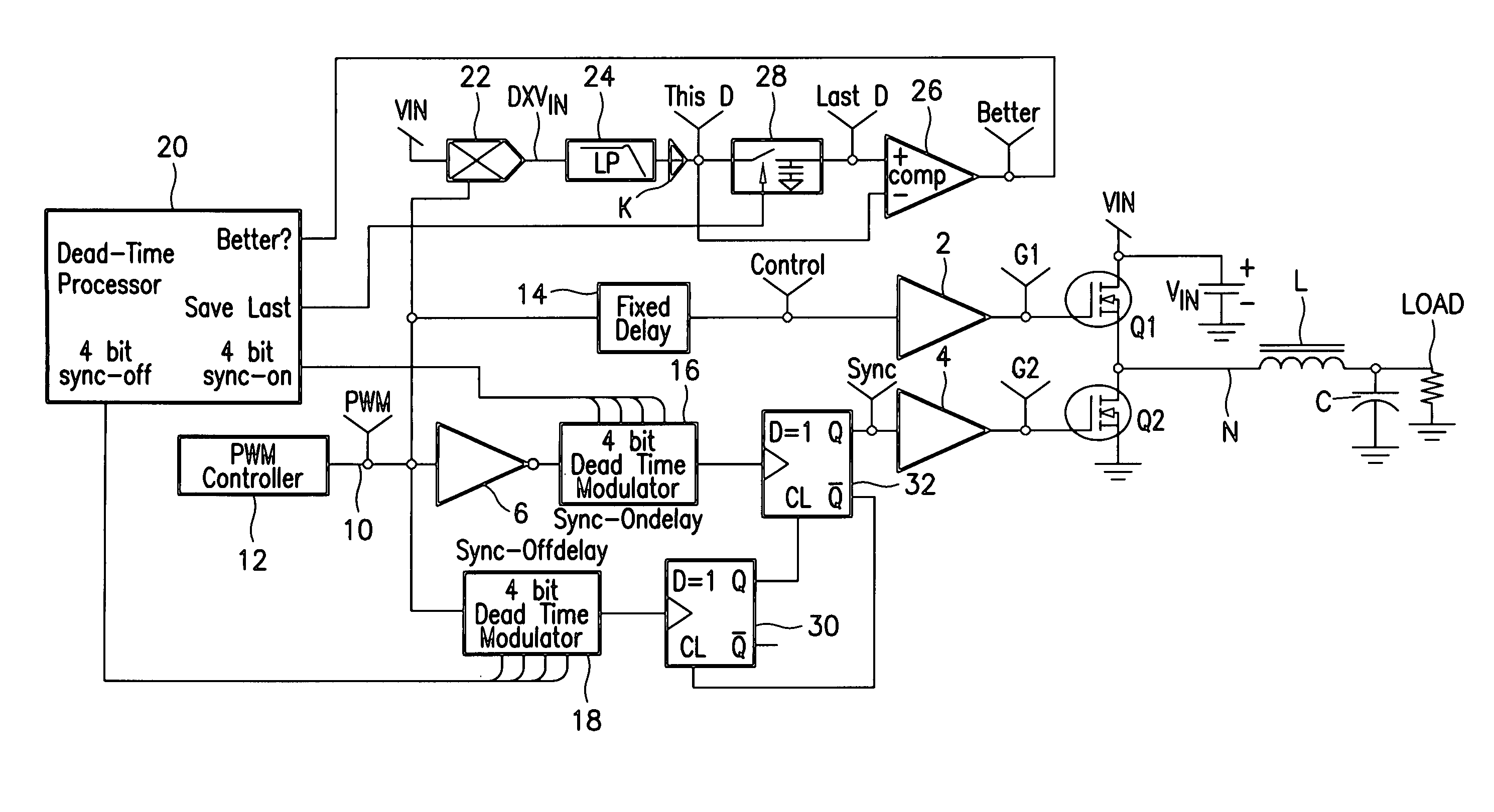
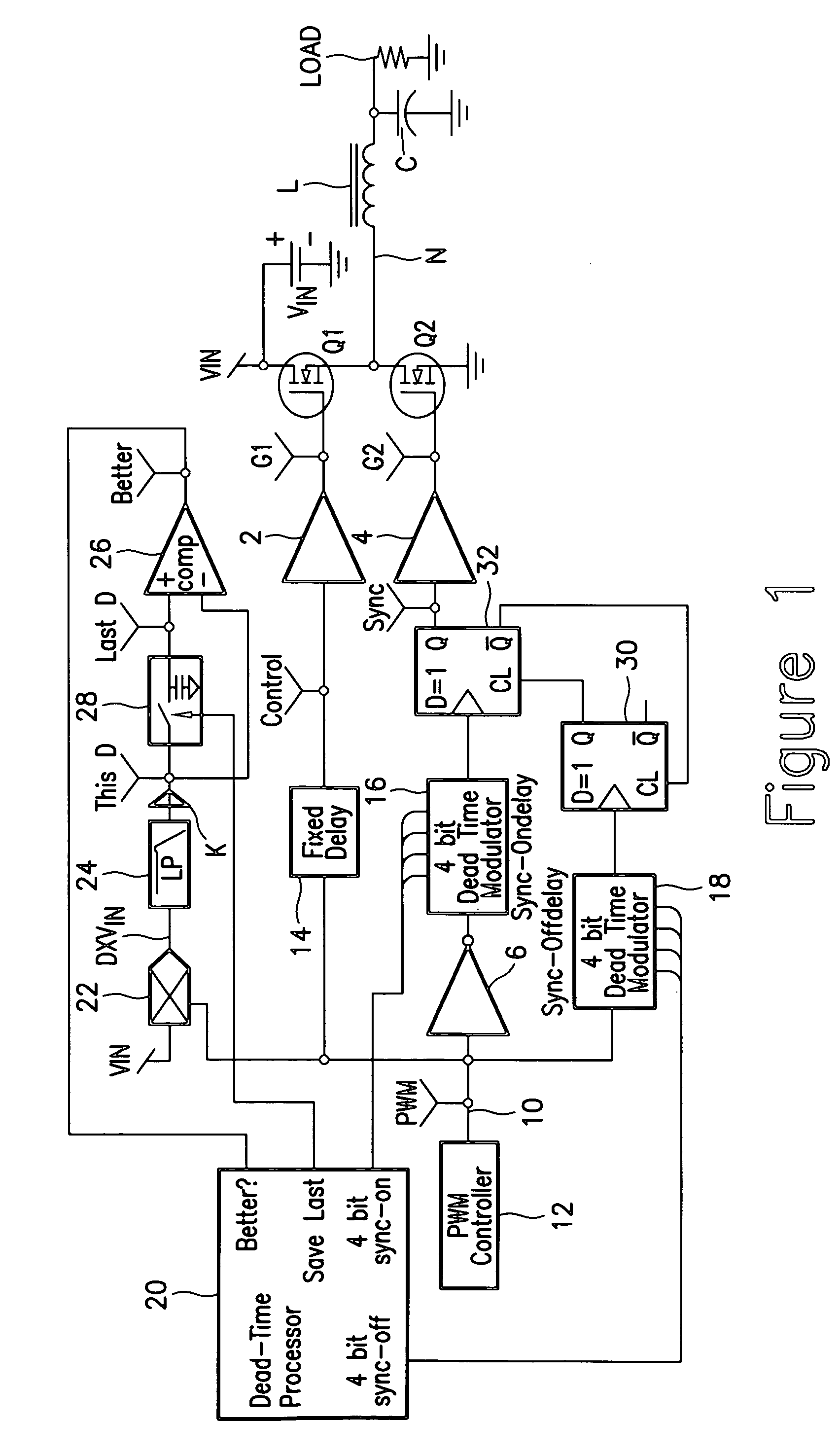
[0026] Turning now to the drawings, FIG. 1 shows one possible implementation of the present invention which combines digital and analog circuitry. Others are possible and most blocks and functions can be implemented with digital circuitry as well as analog.

[0027]FIG. 1 shows a DC-DC converter circuit that has been modified to incorporate the technique according to the present invention to minimize power losses during dead time. The converter includes two switches, Q1 and Q2, typically MOSFETs, connected in series between the power supply nodes VIN and ground. The converter shown is a buck converter, but the invention is applicable to any form of switching mode power supply with synchronous rectification.

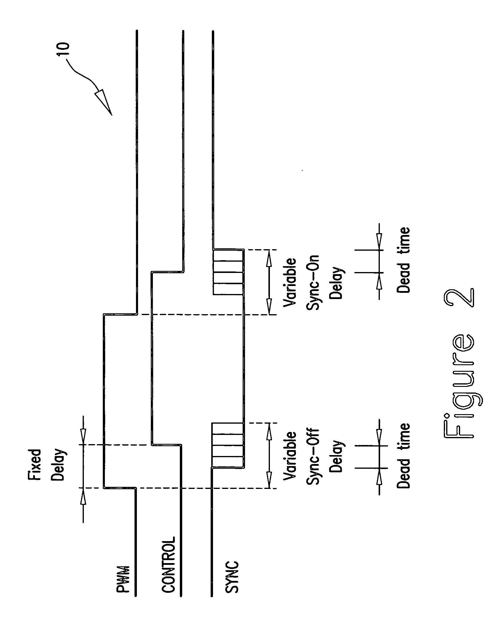
[0028] As well known, the switched node N of a buck converter is coupled to the load through an output inductor L. An output capacitor C is coupled across the load. The gate of each switch Q1 and Q2 is coupled to pulse width modulated (PWM) signals from a PWM controller 12 via gate...


PUM


Abstract

Apparatus for minimizing power losses associated with dead time between ON times of two series connected switches of a power converter connected across a supply potential, the apparatus comprising a control arrangement for monitoring a selected parameter associated with power loss during the dead time of the converter; the control arrangement changing the dead time from a first dead time to a second dead time and comparing power loss associated with the selected parameter for the first and second dead times and determining which of the power losses associated with the two dead times is smaller; a dead time implementing stage for implementing the two dead times; and the control arrangement selecting the dead time associated with the smaller power loss and providing a signal to the dead time implementing stage to set the selected dead time.

Description

CROSS REFERENCE TO RELATED APPLICATIONS [0001] This application claims the benefit and priority of U.S. Provisional patent application Ser. No. 60 / 546,374 filed Feb. 20, 2004 entitled POWER LOSS MINIMIZING DEAD TIME, the entire disclosure of which is incorporated herein by reference.BACKGROUND OF THE INVENTION [0002] The present invention relates to power supplies and in particular to voltage converters employing two controlled switches, one of which operates as a synchronous rectifier. The two switches are generally controlled so that both switches are never on at the same time. A “dead time” is provided between the on-times of the two switches to prevent cross conduction across the DC voltage supply between which the two switches are connected in series. [0003] Synchronous rectification has been widely adopted for use in low voltage output converters of various topologies: buck, boost, flyback and forward. By substituting a MOSFET switch for a silicon or Schottky diode, rectificat...

Claims


Application Information

Patent Timeline
IPC IPC(8): G05F1/40H02M1/38
CPCH02M1/38G05F1/10G05F1/40
Inventor BROWN, JAMES S.
Owner INFINEON TECH AMERICAS CORP
Why Eureka
Try Eureka