Recording medium, recording apparatus and recording method

a recording medium and recording apparatus technology, applied in the field of data recording medium, can solve the problems of affecting the cooling process of the preceding mark, affecting the heat distribution, and significant loss of signal quality, and achieve the effect of reducing jitter

Inactive Publication Date: 2005-08-25
SHOJI MAMORU +3
View PDF10 Cites 7 Cited by
  • Summary
  • Abstract
  • Description
  • Claims
  • Application Information

AI Technical Summary

Benefits of technology

[0128] According to the 61st aspect of the invention, in the recording method as set forth in the 57th aspect, group delay compensation is performed to minimize jitter in the reproduced test signal.

Problems solved by technology

In a direct overwrite recording method this can result in part of a mark not being overwritten or completely erased, resulting in a significant loss of signal quality due to signal crosstalk between tracks during reproduction.
This thermal interference can result in heat at the trailing edge of a recorded mark travelling through the following space, thus affecting heat distribution at the beginning of the next mark.
Heat at the beginning of one recorded mark can also travel back through the preceding space and adversely affect the cooling process of the preceding mark.
When such thermal interference occurs with conventional recording methods, the positions of the leading and trailing edges can shift, thus increasing the error rate during data reproduction.
Japanese Patent Application 5-279513 does not, however, teach a method for determining the optimum positions of the leading and trailing parts of a mark.
If the method of optimizing the leading and trailing edge positions is not defined, the reliability of the optimized recording will be low.
Furthermore, even if optimized recording is achieved, it will be at the expense of excessive time spent searching for the optimum position and excessive circuit cost.
A problem with this method, however, is that the edge of a recorded mark can move due to thermal interference as described above.

Method used


Image

  • Recording medium, recording apparatus and recording method
  • Recording medium, recording apparatus and recording method
  • Recording medium, recording apparatus and recording method

Examples


Embodiment Construction

[0177] The preferred embodiments of the present invention are described below with reference to the accompanying figures.

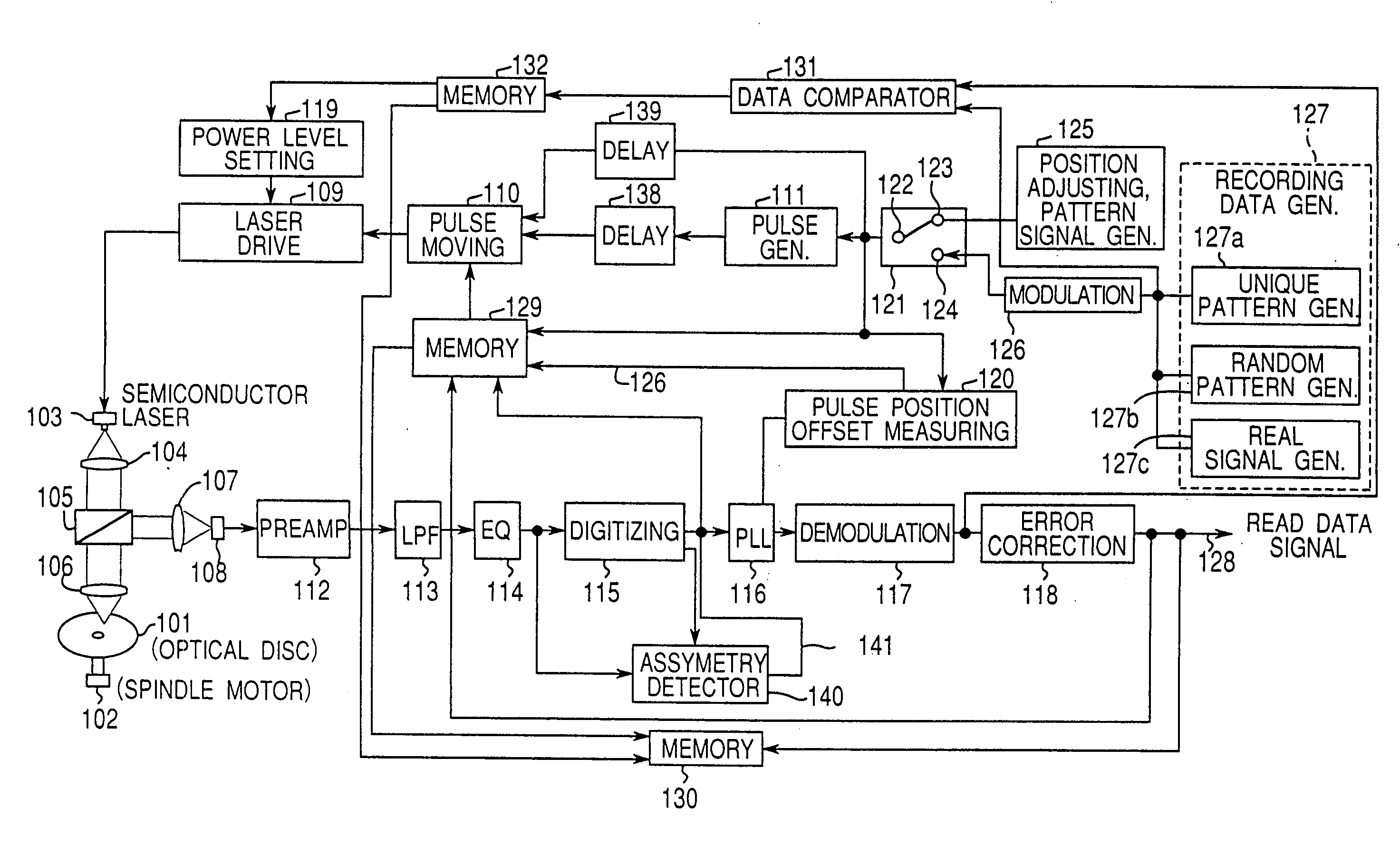
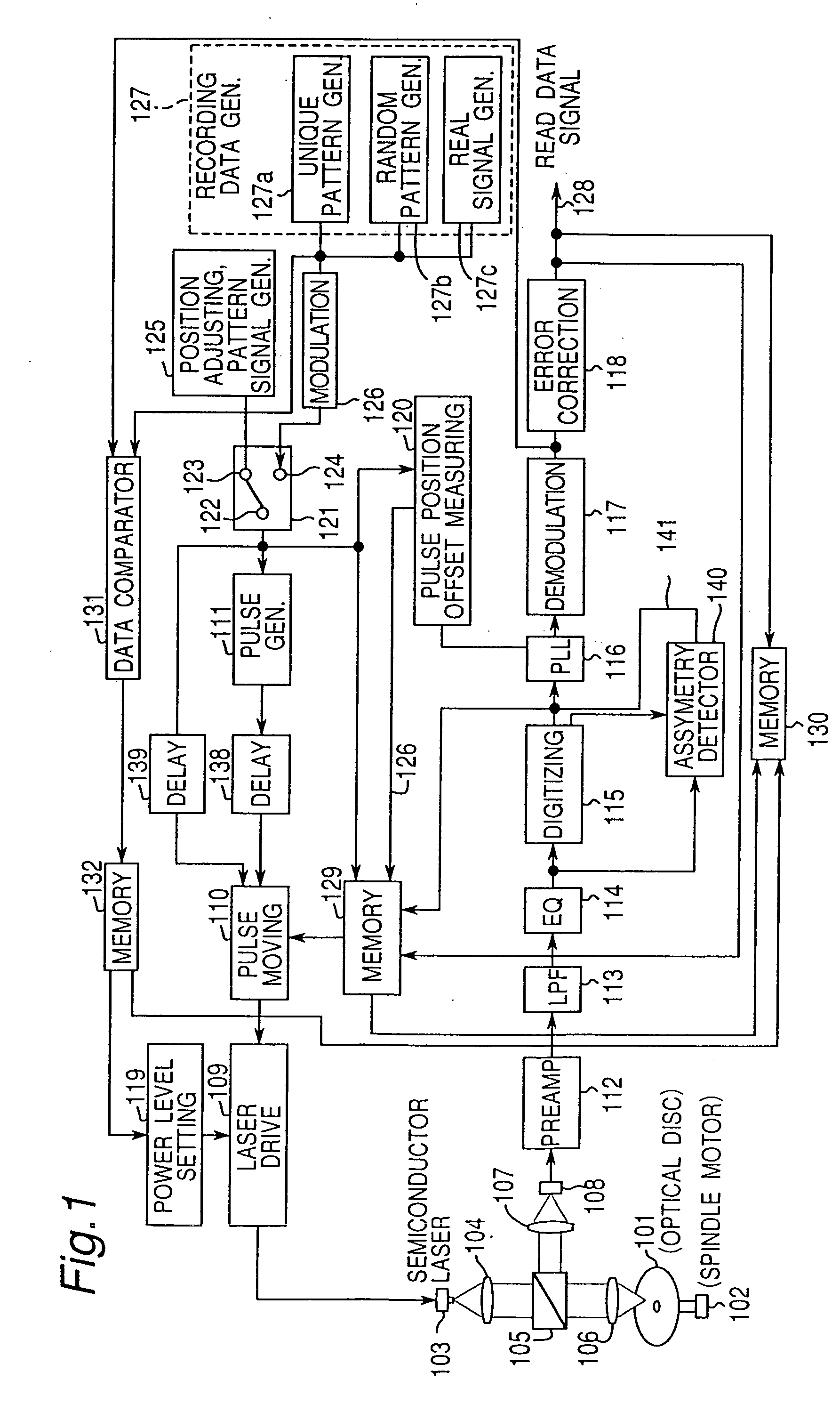
[0178]FIG. 1 is a block diagram of an optical data recording apparatus, referred to below as an optical disc recorder, according to the preferred embodiment of the present invention.

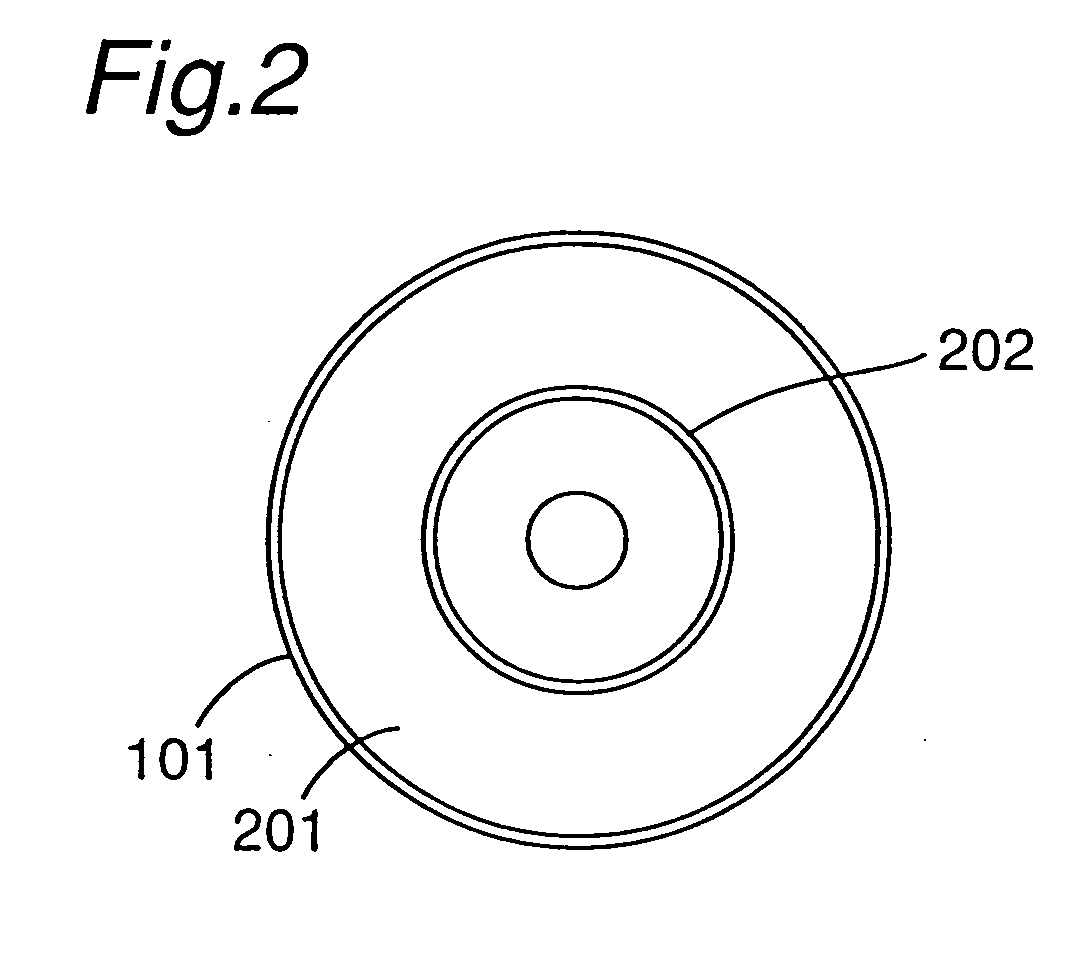
[0179] Shown in FIG. 1 are: an optical disc 101, spindle motor 102, semiconductor laser 103, collimeter lens 104, beam splitter 105, objective lens 106, collective lens 107, photodetector 108, laser drive circuit 109, pulse moving circuit 110, pulse generator 111, preamplifier 112, low pass filter 113, reproduction equalizer 114, digitizing circuit 115, PLL 116, demodulation circuit 117, error correction circuit 118, power level setting circuit 119, pulse position offset measuring circuit 120, switch 121, switch contacts 122, 123, and 124, pattern signal generator 125 for pulse position adjusting, modulation circuit 126, recording data generator 127, read data signal 128, memory 129,...


PUM

PropertyMeasurementUnit
lengthaaaaaaaaaa
lengthaaaaaaaaaa
lengthaaaaaaaaaa

Abstract

Optimum movement of first and last signal pulses based on the data pattern is determined before data recording to record marks in the correct position. A specific pattern signal is read from a disc track and digitized with an appropriate slice level by the digitizing circuit (115). A pulse position offset measuring circuit (120) then measures specific edge intervals in the resulting digital signal. Movement of the first and last pulse by the pulse moving circuit (110) is then set so that the offset between the measured edge interval and a predetermined standard edge interval is ideally zero.

Description

BACKGROUND OF THE INVENTION [0001] 1. Field of the Invention [0002] The present invention relates to a data recording medium, a recording apparatus and to a recording method for recording information to this data recording medium. [0003] 2. Description of Related Art [0004] Data recording devices for optically recording information, and particularly digital data, to a storage medium are commonly used as a convenient means of mass data storage. [0005] Phase change optical discs are one type of optical data recording medium. To record to a phase change optical disc a semiconductor laser emits an optical beam to a spinning disc to heat and melt a recording film on the disc. The achieved temperature and the cooling process (rate) of the molten film can be regulated by controlling the power of the laser beam, thereby inducing a phase change in the recording film. [0006] When laser power is high, the recording film cools rapidly from a high temperature state and thus becomes amorphous. Wh...

Claims


Application Information

Patent Timeline
Patent Type & Authority Applications(United States)
IPC IPC(8): G11B5/09G11B7/0045G11B7/00G11B7/0037G11B7/005G11B7/006G11B7/007G11B7/013G11B7/125G11B7/24G11B7/26G11B19/12G11B20/10G11B20/12
CPCG11B7/0045G11B7/00454G11B7/00456G11B7/006G11B7/0062G11B7/007G11B20/1217G11B7/126G11B7/24085G11B7/261G11B20/10194G11B20/10212G11B7/00736G11B7/005G11B7/0079G11B2220/2537G11B2020/1265
Inventor SHOJI, MAMORUISHIDA, TAKASHINAKAMURA, ATSUSHIMINAMINO, JUNICHI
Owner SHOJI MAMORU
Why Eureka
Try Eureka