Dynamic reactive compensation system and method

a reactive compensation and dynamic technology, applied in the field of electric power utility networks, can solve problems such as voltage instability, voltage collapse, voltage instability on the grid, etc., and achieve the effects of reducing the opportunity for reducing the tendency for voltage collapse, and reducing the chance of unstable behavior and/or oscillation

Inactive Publication Date: 2005-09-08
AMERICAN SUPERCONDUCTOR
View PDF52 Cites 95 Cited by
  • Summary
  • Abstract
  • Description
  • Claims
  • Application Information

AI Technical Summary

Benefits of technology

[0027] The system and method are capable of attenuating rapid voltage variations and for providing post-fault voltage support to mitigate any tendency for voltage collapse. In addition to acting as a fast transient voltage support device, the system is also capable of regulating voltage at a point on the transmission or distribution grid and minimizing transients imposed on the fundamental waveform of a normal voltage carried on a utility power network when a reactive power source (e.g., capacitor bank) is connected to the utility power network. By integrating the dynamic VAR output of the reactive power compensation device (e.g., inverters) with very fast (e.g., 24 msecs) mechanically switched capacitor and reactor banks, the system becomes a very economical alternative to SVC's and equally effective at solving common transmission grid problems such as voltage instability and voltage regulation. SVC's and STATCOMs are faster than necessary to solve these problems and are very costly. Conventional mechanically switched reactive devices, while of acceptable spe

Problems solved by technology

Voltage instability on the utility power grid is a critical problem for the utility industry.
In particular, when a fault occurs on the transmission grid, momentary voltage depressions are experienced, which may result in voltage collapse or voltage instability on the grid.
In general, such a fault appears as an extremely large load materializing instantly on the transmission system.
However, opening of the breakers triggers a sequence of events, which in the extreme can cause that portion of the transmission and distribution system to collapse.
Specifically, when the breakers open, the voltage is still low (i.e., almost zero) and, because a portion of the transmission system has in effect been removed, the impedance of the system dramatically increases causing the appearance of an artificially high load.
The sharp increase in the current generates enormous losses in the transmission and distribution systems.
In some cases, because the load and impedance are high, the voltage on the grid may not return to normal, causing long-term voltage depression and the possible voltage collapse of the entire system.
The potential for these v

Method used


Image

  • Dynamic reactive compensation system and method
  • Dynamic reactive compensation system and method
  • Dynamic reactive compensation system and method

Examples


Embodiment Construction

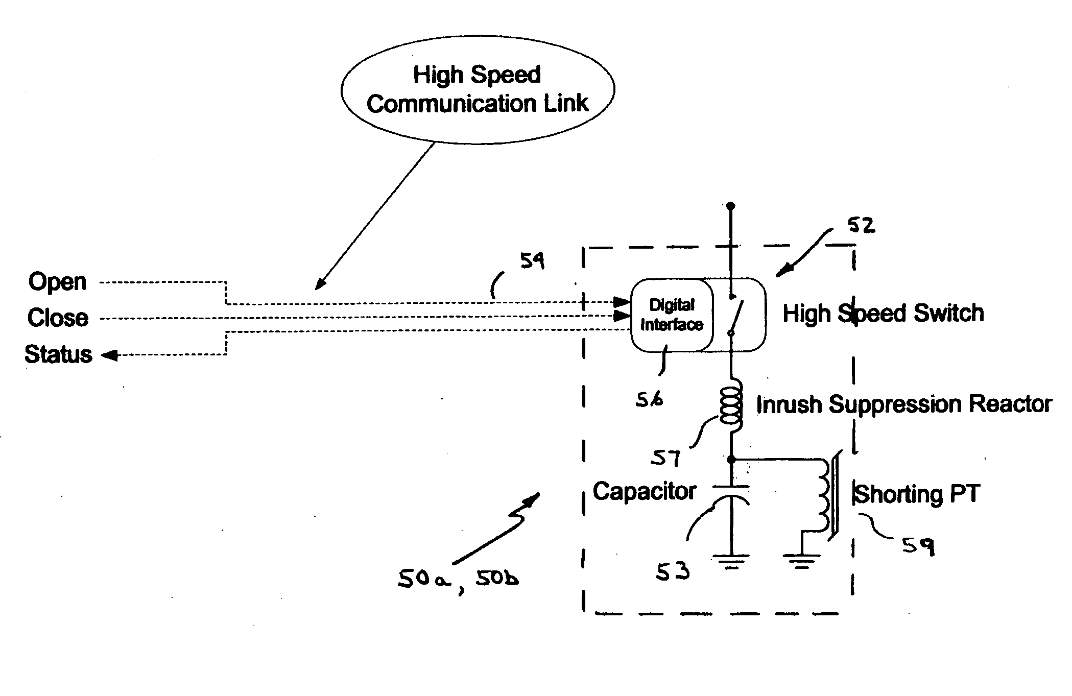
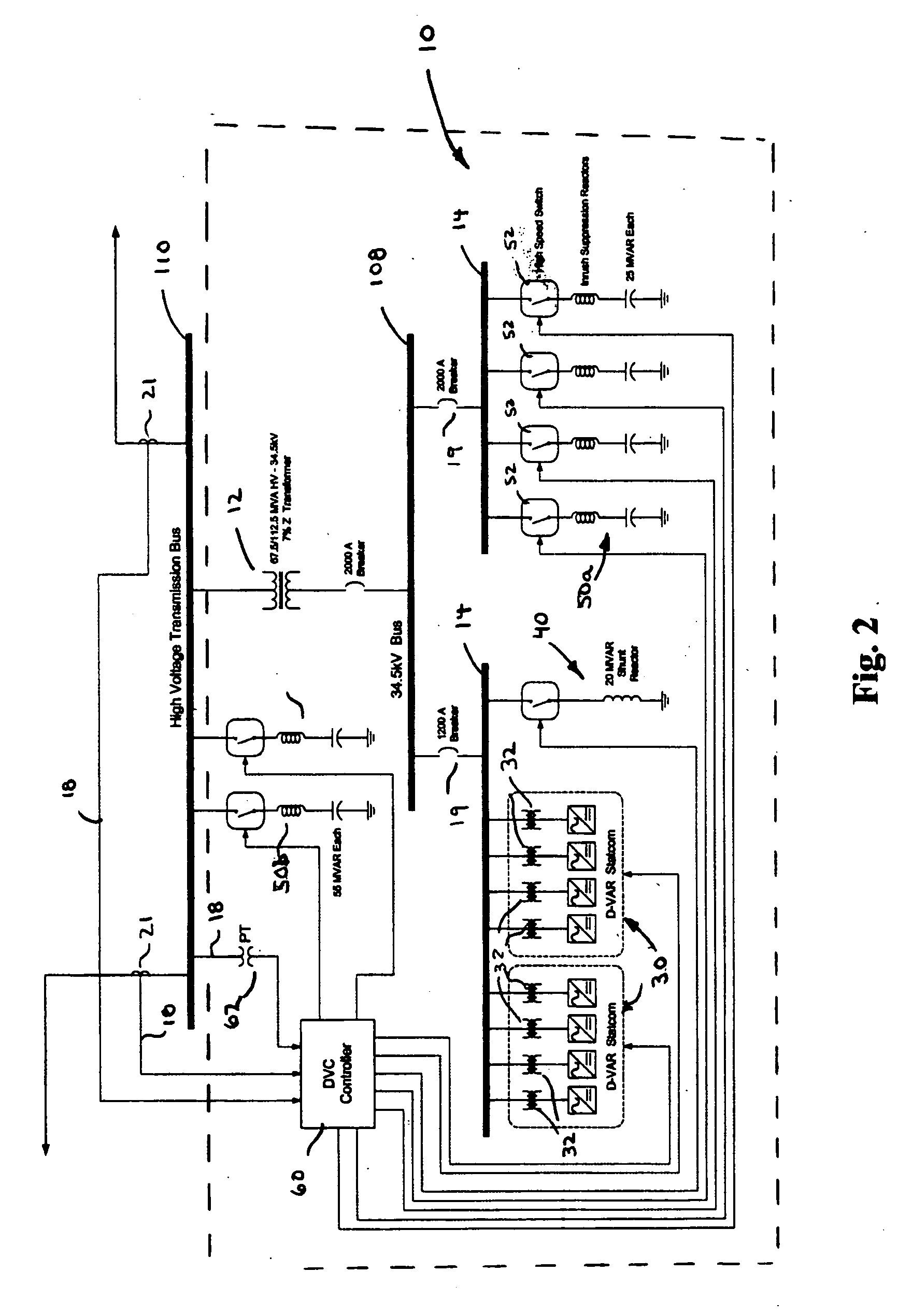
[0037] Referring to FIG. 2, a dynamic voltage system 10 is shown connected in shunt with a transmission line 110 of a utility power network via a first transformer 12, which steps down the higher voltage (e.g., greater than 35 kV carried on transmission line 110 to a lower voltage, here 34.5 kV, of a medium voltage bus 108. Dynamic voltage system 10 includes, in this embodiment, a pair of D-VAR® statcom systems 30, each of which are coupled to an internal bus 14 with summing transformers 32. D-VAR® statcom systems 30 are available from American Superconductor Corporation, Westboro, Mass. Because each D-VAR® statcom system 30 has a nominal 480 VAC output, two stages of transformation (transformers 12 and 32) to interface to a high voltage transmission system are used.

[0038] Dynamic voltage system 10 also includes a shunt reactor 40 and, in this embodiment, four capacitor banks 50a, each coupled to internal bus 14. Shunt reactor 40 provides negative (inductive) VARs over and above th...


PUM


Abstract

The invention features a system for connection to a utility power network. The system includes a reactive power compensation device coupled to the network and configured to transfer reactive power between the utility power network and the reactive power compensation device; a capacitor system configured to transfer capacitive reactive power between the utility power network and the capacitor system; an electro-mechanical switch for connecting and disconnecting the capacitor system to the utility power network; an interface associated with the electro-mechanical switch; a controller configured to provide control signals for controlling the electro-mechanical switch; and a communication channel for coupling the controller to the interface associated with the electro-mechanical switch. The electro-mechanical switch, interface, controller, and communication channel together are configured to connect or disconnect the capacitor system from the utility power network within about three line cycles or less of the nominal voltage frequency when a fault condition is detected on the utility power network.

Description

BACKGROUND OF THE INVENTION [0001] This invention relates to electric power utility networks including generating systems, transmission systems, and distribution systems serving loads. [0002] To remain competitive, electrical utility companies continually strive to improve system operation and reliability while reducing costs. To meet these challenges, the utility companies are developing techniques for increasing the life of installed equipment, as well as, diagnosing and monitoring their utility networks. Developing these techniques is becoming increasingly important as the size and demands made on the utility power grid continue to increase. A utility power grid is generally considered to include both transmission line and distribution line networks for carrying voltages greater than and less than about 35 kV, respectively. [0003] Voltage instability on the utility power grid is a critical problem for the utility industry. In particular, when a fault occurs on the transmission gr...

Claims


Application Information

Patent Timeline
IPC IPC(8): G05F1/70H02J3/18
CPCY02E40/30H02J3/1828
Inventor FOLTS, DOUGLAS C.VAREKA, WILLIAM A.KEHRLI, ARNOLD P.DIAZ DE LEON, JOHN A. II
Owner AMERICAN SUPERCONDUCTOR
Why Eureka
Try Eureka