Continuous resin recovery apparatus and recovery method

a technology of recovery apparatus and resin, which is applied in the direction of lighting and heating apparatus, separation processes, evaporation, etc., can solve the problems of unavoidable generation of dust from sliding parts, volatile contents, and no known method to obtain optically satisfying resins by directly filtering molten resins. achieve the effect of high productivity

Inactive Publication Date: 2005-09-08
ASAHI GLASS CO LTD
View PDF1 Cites 9 Cited by
  • Summary
  • Abstract
  • Description
  • Claims
  • Application Information

AI Technical Summary

Benefits of technology

[0007] The present invention provides a continuous resin recovery apparatus for continuously drying a resin solution and recovering resin from which a solvent is removed, the continuous resin recovery apparatus being characterized by comprising a liquid-feeding means for feeding the resin solution, a heating pipe for heating the resin solution, a rough drying chamber that is depressurized and in which the heated resin solution is introduced, and a precise drying chamber that is depressurized and is located underneath the rough drying chamber so that the molten resin roughly dried can flow down to be introduced in the precise drying chamber, wherein a perforated plate through which the molten resin flows is horizontally provided in the precise drying chamber. According to the recovery apparatus for resin, the resin from which volatile contents are removed sufficiently can be recovered at high productivity.

Problems solved by technology

In the existing techniques, there is no known method to obtain an optically satisfying resin by directly filtering a molten resin.
However, in a case of the resin for optical use, volatile contents also need to be removed at the same time.
However, it was unavoidable to generate dust from the sliding part.
Further, in the method described in JP-A-2000-102921, resin solution of low concentration could not be directly treated on the basis that drying method is for a high viscosity fluid.
Namely, the resin solution of low concentration and low viscosity, from which foreign matters should be sufficiently removed by filtering, could not be treated.
Further, in the above “CRUX System”, there have been problems that the method can not reduce the amount of residual solvent to a level required for the optical resin, and that prevention of contamination is difficult because the resin obtained contains bubbles and foreign matters tend to be involved in the resin when the resin is taken out of the apparatus.
Thus, heretofore, there has not been known any recovery apparatus or recovery method for resin in which foreign matters and volatile contents are removed sufficiently from the resin and interfusion of foreign matters can be prevented and for permitting continuous process.

Method used


Image

  • Continuous resin recovery apparatus and recovery method

Examples


example

[0044] The continuous resin recovery method of the present invention will be described with reference to the following Example. Here, the reference numerals of the apparatus are the same as ones described in the explanation of FIG. 1.

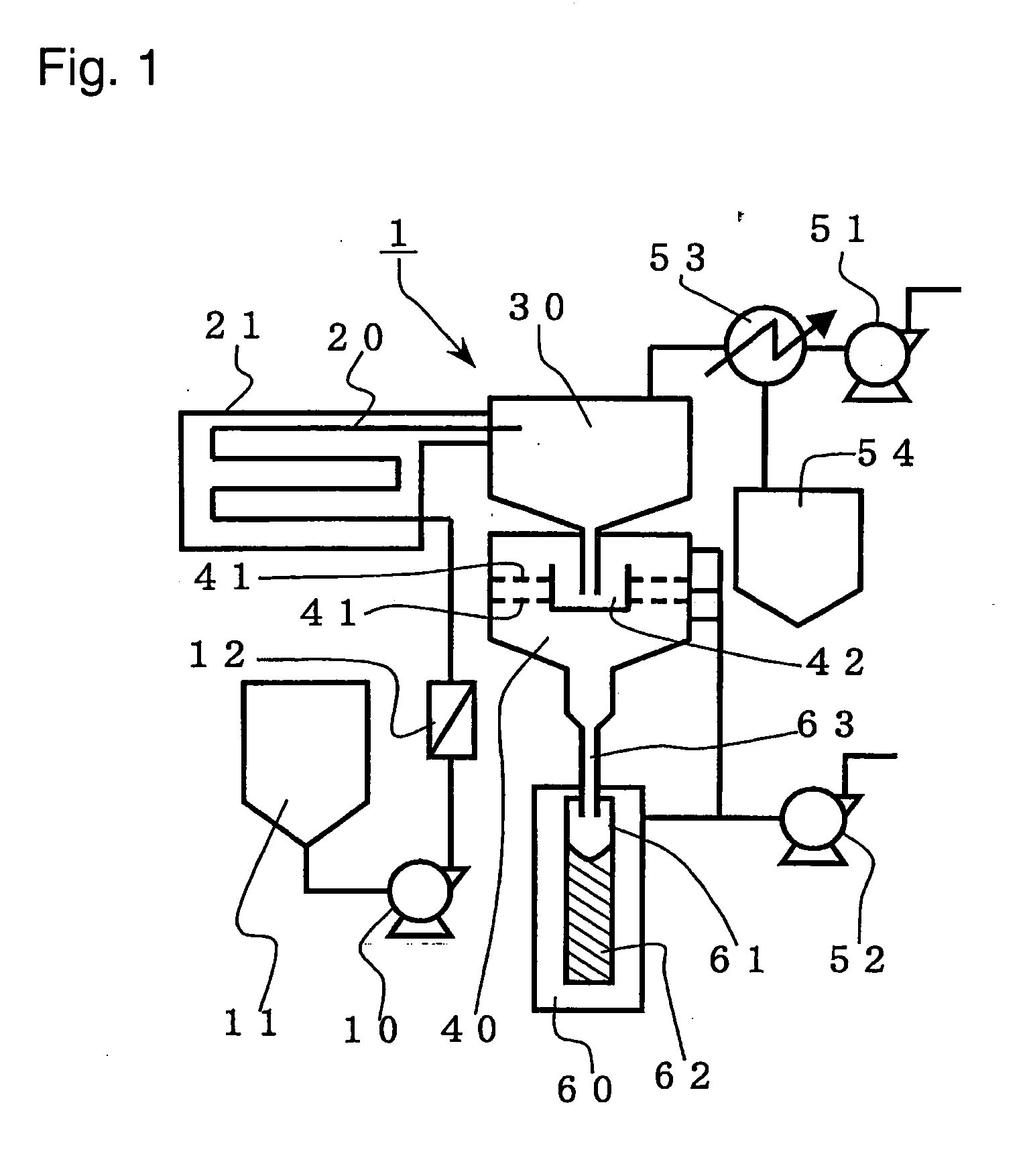
[0045] A resin recovery apparatus 1 employed was as follows. A raw liquid tank 11 is a vessel made of a stainless steel having a volumetric capacity of about 70 L. A liquid-feeding pump 10 is a diaphragm pump manufactured by Nikkiso Eiko Co., Ltd. having a maximum liquid-feeding capacity of 0.14 L / min. The material of the diaphragm is a polytetrafluoroethylene resin. A filtering device 12 is a cartridge type filtering device having a mesh size of 0.07 μm and a length of cylindrical part of about 26 cm, and the material of a filtering surface is a polyethylene resin. A heating pipe 20 is a pipe made of a stainless steel having an inner diameter of 4.86 mm, a length of 23.8 m and a length of final straight part of 80 cm.

[0046] A drying chamber 30 is a c...


PUM

PropertyMeasurementUnit
sizeaaaaaaaaaa
sizeaaaaaaaaaa
sizeaaaaaaaaaa

Abstract

The present invention provides a continuous resin recovery method for recovering resin from which foreign matters and volatile components are sufficiently removed and which is highly purified and suitable for optical use. The continuous resin recovery method comprises a step of heating a resin solution in a heating pipe at a temperature at least the boiling point of the solvent, a step of introducing the resin solution heated at a temperature at least the boiling point of the solvent into a rough drying chamber maintained at a reduced pressure, a step of separating the resin from the solvent vapor in the rough drying chamber, a step of melting the separated resin, a step of introducing the molten resin in a precise drying chamber kept at a reduced pressure, and a step of passing the molten resin through a perforated plate in the precise drying chamber.

Description

TECHNICAL FIELD [0001] The present invention relates to a continuous resin recovery apparatus and a recovery method in which a resin solution is dried to remove sufficiently volatile contents. More specifically, the present invention relates to a continuous resin recovery apparatus and a recovery method for recovering resin suitable for optical use from which foreign matters and volatile contents are removed sufficiently and which is highly purified. BACKGROUND ART [0002] Purification process of resin usable for semiconductor use or optical use is required to remove foreign matters and volatile contents as much as possible to obtain a highly purified resin. In particular, in a case of resin for plastic optical fibers, it is required to reduce scattering and absorption which prevent propagation of light, to an extremely low level. [0003] In order to remove foreign matters from the resin, filtering is the most suitable method. Here, a method of precisely filtering a raw material of re...

Claims


Application Information

Patent Timeline
Patent Type & Authority Applications(United States)
IPC IPC(8): B01D1/00B01D1/02B01D1/18C08F6/00C08F6/12C08F6/28F26B5/04
CPCB01D1/0017B01D1/02B01D1/18F26B5/041C08F6/005C08F6/12C08F6/28C08F6/003C08F6/00C08F6/10
Inventor KURASHIMA, KAZUYOSHISUMI, YOSHITERUETOH, YASUOMINEZAKI, KUMIKONINOMIYA, DAISUKE
Owner ASAHI GLASS CO LTD
Why Eureka
Try Eureka