Bio-photonic-scanning calibration method

a biophotonic scanning and calibration method technology, applied in the field of optical measurement of light intensity, can solve the problems of inherently problematic calibration samples taken from biological materials, inability to portability a sample, and inability to accurately measure the intensity of light, so as to achieve reliable radiant responses, improve signal-to-noise ratio, and improve the effect of raman respons

Inactive Publication Date: 2005-09-08
NU SKIN INT
View PDF11 Cites 11 Cited by
  • Summary
  • Abstract
  • Description
  • Claims
  • Application Information

AI Technical Summary

Benefits of technology

[0021] In accordance with the foregoing needs, a system of various apparatus and methods is disclosed herein for calibrating bio-photonic scanning systems. Moreover, synthetic materials have been discovered, formulated, evaluated, and otherwise made available to perform the various calibration functions required of a bio-photonic scanner. For example, mechanisms have been developed for presenting to a scanner calibration materials in repeatable structures and positions in order to obtain reliable radiant responses therefrom. Likewise, various compositions for factory and field calibration operations have been developed. For example, a dark cap for returning substantially no radiant response to a scanner, in response to laser illumination, provides for a mechanism to factor out the electrical and electronic artifacts of the machine. Similarly, a white scan sample has been developed that replicates the shape and values of the spectral response of biological tissues, while being reproducible as a simple non-biological chemical composition. Moreover, materials have been discovered and developed for doping a matrix of material in order to present synthetic mimics of certain molecular structures of interest. For example, carotenoids and other chemical compositions existing in biological tissue appear to contain certain characteristic carbon bond structures. Synthetic materials have been discovered that contain similar bond structures, responsive to illumination by providing a radiant response (e.g. Raman scattering, etc.) similar to that of biological molecular constituents. Accordingly, a system and method having been developed to implement synthetic materials as calibration samples in order to calibrate scanning systems repeatably. Moreover, the various compositions and apparatus developed and discovered have been implemented successfully in a series of calculations and mathematical manipulations of data in order to process the output of a scanner, normalizing and otherwise neutralizing undesirable or uninteresting characteristics of spectral curves of radiant intensity. Thus, machine-to-machine variations as well as time-to-time variations within a single machine can be factored out, yielding much better signal to noise ratios and much more evident Raman responses. Accordingly, proper calibration apparatus and methods provide for accurate and repeatable utility of bio-photonic scanner.

Problems solved by technology

Nevertheless, the variation between electronic components is not negligible.
Nevertheless, the portability of a sample may be problematic.
Calibration samples taken from biological materials are inherently problematic.
In either event, the amount of a sample, the repeatablility of a sample, the control and observable characteristics of a sample are nearly impossible to maintain when dealing with biological materials.
Moreover, the replication of biological materials, organisms, tissues, or other substances is extremely difficult.
Moreover, the variation in conditions cannot be precisely controlled in many circumstances.
Providing identical conditions, genetics, and the like in an organism is not a practical mechanism for generating calibration samples.
On the other hand, collection of such detailed data may be impossible.
As a practical matter, such collection and analysis can be extremely complex and prohibitively expensive.

Method used


Image

  • Bio-photonic-scanning calibration method
  • Bio-photonic-scanning calibration method
  • Bio-photonic-scanning calibration method

Examples


Embodiment Construction

[0053] It will be readily understood that the components of the present invention, as generally described and illustrated in the Figures herein, could be arranged and designed in a wide variety of different configurations. Thus, the following more detailed description of the embodiments of the system and method of the present invention, as represented in FIGS. 1 through 19, is not intended to limit the scope of the invention, as claimed, but is merely representative of certain presently illustrated embodiments of the invention.

[0054] The various embodiments in accordance with the invention will be best understood by reference to the drawings, wherein like parts are designated by like numerals throughout.

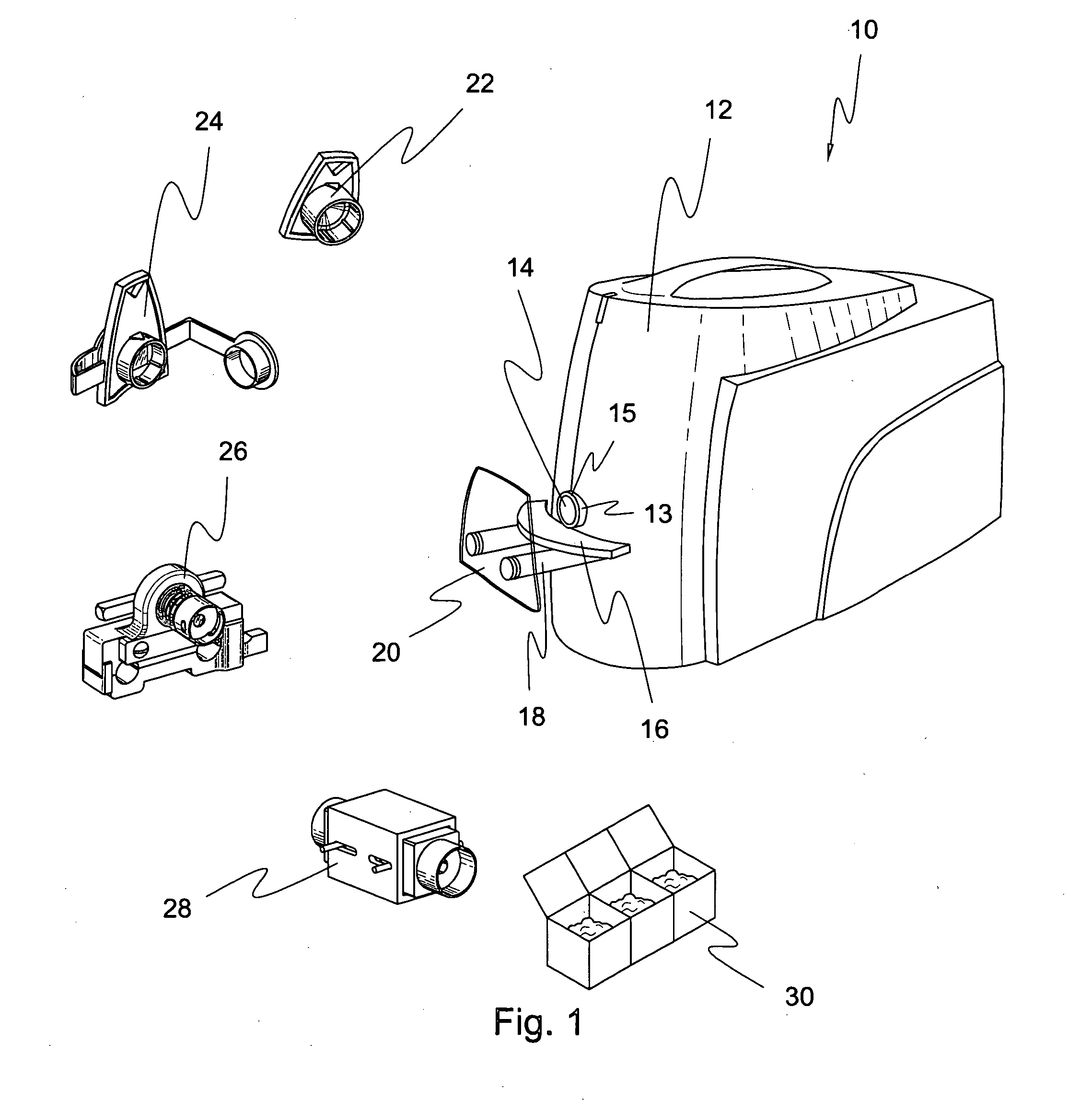
[0055] Referring to FIG. 1, an apparatus 10 in accordance with the invention may include a scanning mechanism including a power supply, a light source, such as a laser light source, and a detector. The detector may receive signals including background fluorescence, elastically scat...


PUM


Abstract

Methods, apparatus, and compositions calibrate a bio-photonic scanner detecting selected molecular structures of tissues, nondestructively, in vivo. The apparatus may include a processor, memory, and scanner. The scanner directs light nondestructively onto tissue in vivo, then receives back a radiant response through a system of mirrors and lenses back into the detector. Software for controlling the scanner and processing its output may be calibrated using a synthetic material to mimic the radiant response of tissue. Calibration may account for background fluorescence and elastic scattering, mimicking skin tissue materials having substantially no Raman scattering response of interest. Dopants may be added to the matrix of white scan material to mimic selected molecular structures in tissue. Matrix materials include a dilatant compound, and dopants include biological materials as well as K-type polarizing film and other materials.

Description

RELATED APPLICATIONS [0001] This application claims the benefit of co-pending U.S. Provisional Patent Application Ser. No. 60 / 546,112, filed on Feb. 19, 2004 for SYNTHETIC CALIBRATION STANDARD FOR PHOTONIC RESPONSE OF TISSUES and co-pending U.S. Provisional Patent Application Ser. No. 60 / 545,806, filed on Feb. 19, 2004 for BIO-PHOTONIC SCANNING CALIBRATION APPARATUS AND METHOD.BACKGROUND [0002] 1. The Field of the Invention [0003] This invention relates to optical measurement of intensity of light and, more particularly, to novel systems and methods for calibrating detectors of Raman scattering. [0004] 2. The Background Art [0005] Optical and electronic mechanisms have been developed to generate, detect, observe, track, characterize, process, manipulate, present, and otherwise manage characteristic signals representative of materials, properties, systems, and the like. In the world of engineering, many principles of physics operate predictably, repeatably, and in accordance with the...

Claims


Application Information

Patent Timeline
Patent Type & Authority Applications(United States)
IPC IPC(8): A61B5/00A61B6/00
CPCA61B5/0059G01N21/65A61B2560/0233A61B5/1495A61B6/00G06T15/00
Inventor FERGUSON, SCOTTSTEVENSON, DOUGLASFRALICK, JOHNBRIM, LARRYPETERSON, JACKLAU, KELVINMOORE, ERICGUNDERSON, LYLE
Owner NU SKIN INT
Why Eureka
Try Eureka