Techniques for applying, calibrating, and controlling nerve fiber stimulation

a nerve fiber and vagus nerve technology, applied in the field of stimulation of the vagus nerve, can solve the problems of poor force gradation, muscle fatigue, and reduced cardiac efficiency, and achieve the effect of reducing the side effects of the current application and reducing the heart rate of the subj

Inactive Publication Date: 2005-09-08
MEDTRONIC INC
View PDF99 Cites 318 Cited by
  • Summary
  • Abstract
  • Description
  • Claims
  • Application Information

AI Technical Summary

Benefits of technology

[0136] In some embodiments of the present invention, in which the parameters of the applied bursts include an “on” / “off”ratio, as described herein, the control unit is configured to apply the bursts during short “on” periods and, optionally, to withhold the bursts during short “off”periods. Each of the short “on” periods typically has a duration of less than about 10 seconds, e.g., less than about 5 seconds. When short “off”periods are used, each of the “off”periods typically has a duration of between several seconds and several minutes. The use of such short “on” and / or “off”periods generally allows stimulation of any given strength to be applied as effectively as when using longer “on” / “off”periods, but with fewer potential side effects. For some applications, a desired number of pulses per time period or per heart beat is delivered more effectively and / or with a reduced risk of side effects, by using short “on” periods.
[0591] upon the detection of the ventricular arrhythmia, applying to a site of the subject a current that increases parasympathetic tone of the subject, the site selected from the list consisting of: a vagus nerve of the subject, an epicardial fat pad of the subject, a pulmonary vein of the subject, a carotid artery of the subject, a carotid sinus of the subject, a coronary sinus of the subject, a vena cava vein of the subject, a right ventricle of the subject, and a jugular vein of the subject.

Problems solved by technology

In other conditions, such as atrial fibrillation, increased heart rate variability in an even higher frequency range can cause a reduction in cardiac efficiency by producing beats that arrive too quickly (when the ventricle is not optimally filled) and beats that arrive too late (when the ventricle is fully filled and the pressure is too high).
This unnatural recruitment order causes muscle fatigue and poor force gradation.

Method used


Image

  • Techniques for applying, calibrating, and controlling nerve fiber stimulation
  • Techniques for applying, calibrating, and controlling nerve fiber stimulation
  • Techniques for applying, calibrating, and controlling nerve fiber stimulation

Examples


Embodiment Construction

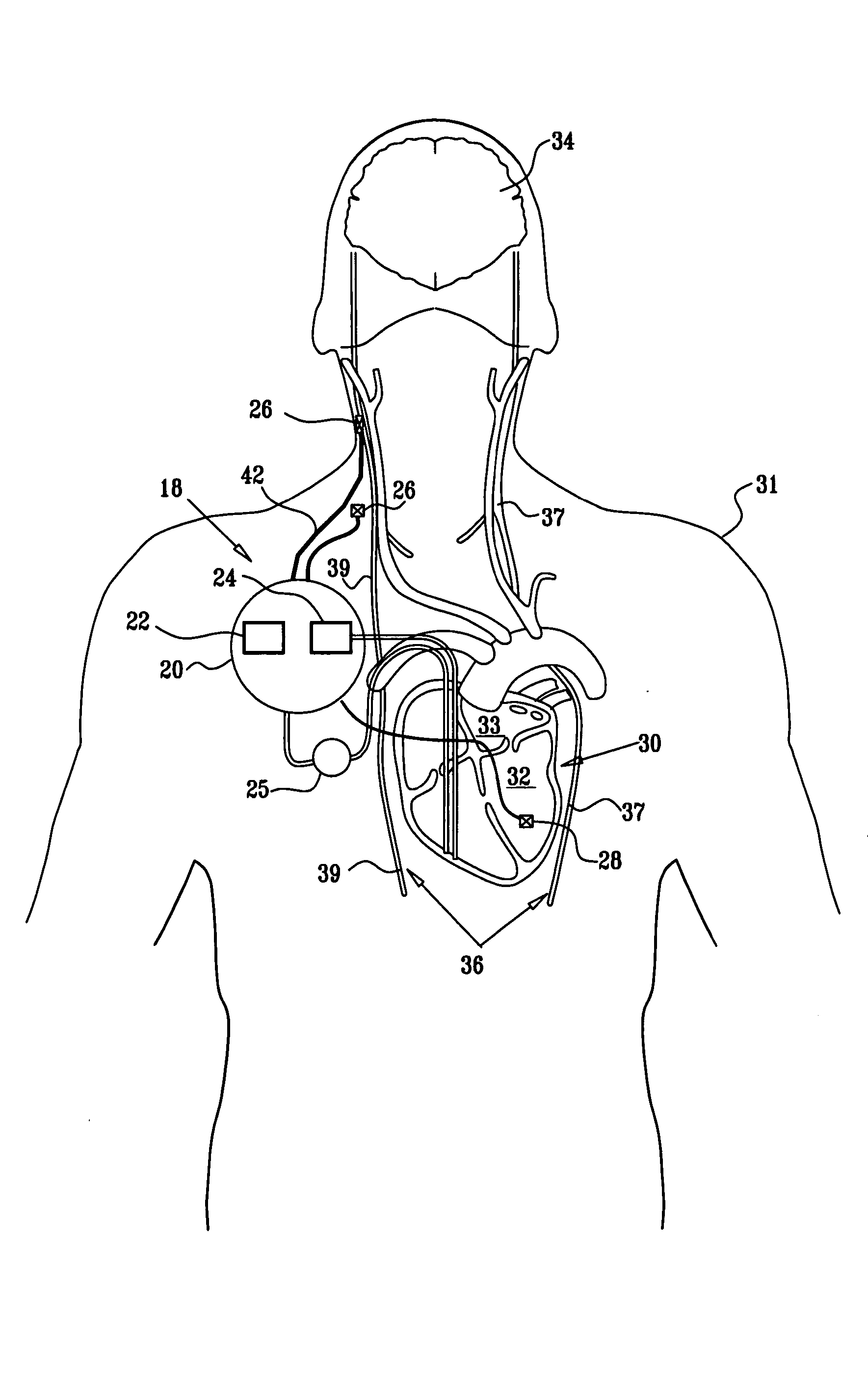
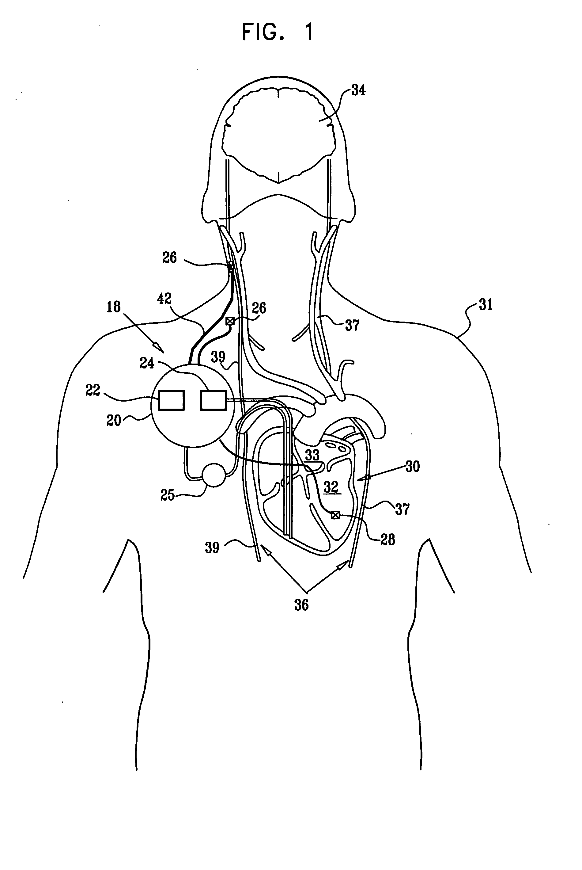
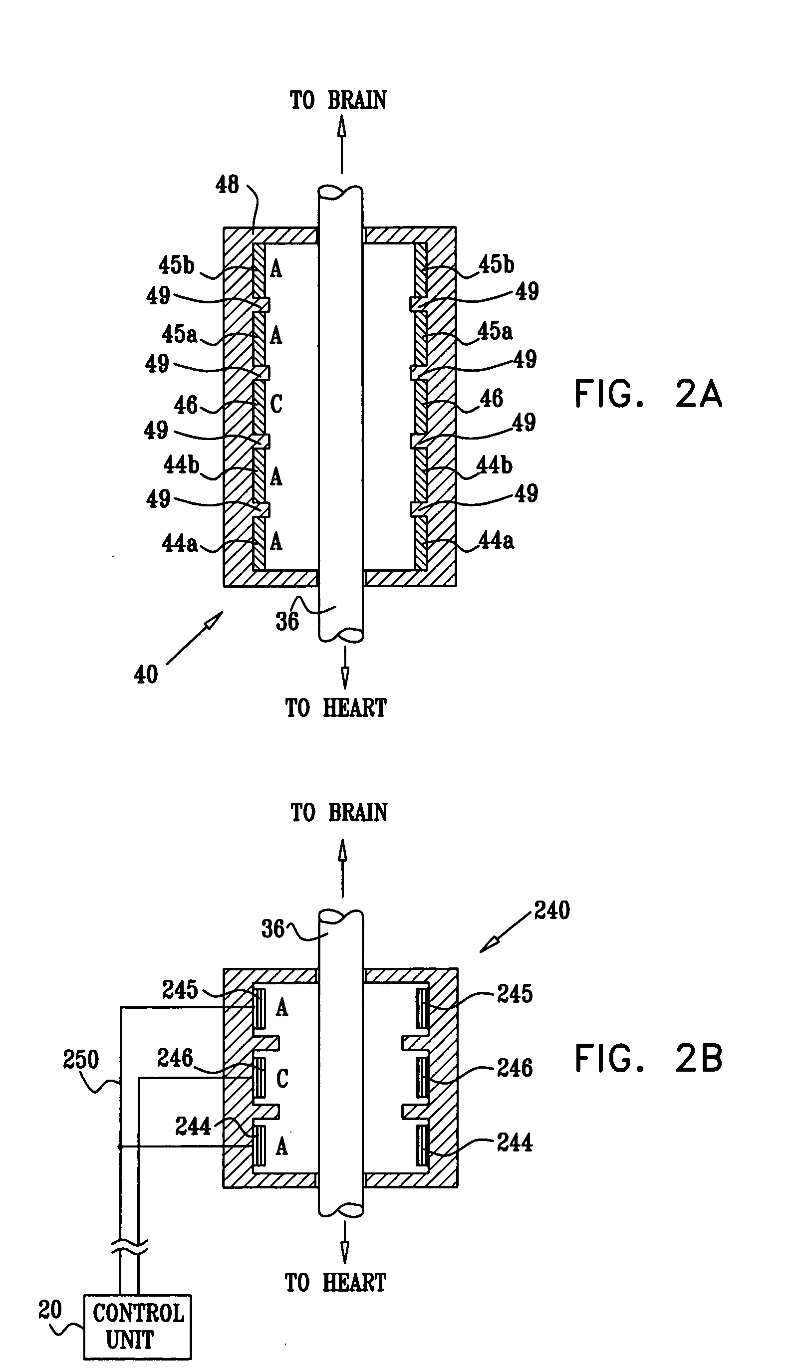
[0628]FIG. 1 is a block diagram that schematically illustrates a vagal stimulation system 18 comprising a multipolar electrode device 26, in accordance with an embodiment of the present invention. Electrode device 26 is applied to a portion of a vagus nerve 36 (a left vagus nerve 37 and / or a right vagus nerve 39), which innervates a heart 30 of a subject 31. Alternatively, electrode device 26 is applied to an epicardial fat pad, a pulmonary vein, a carotid artery, a carotid sinus, a coronary sinus, a vena cava vein, a right ventricle, or a jugular vein (configurations not shown). Typically, system 18 is utilized for treating a heart condition such as heart failure and / or cardiac arrhythmia. Vagal stimulation system 18 further comprises an implantable or external control unit 20, which typically communicates with electrode device 26 over a set of leads 42. Typically, control unit 20 drives electrode device 26 to (i) apply signals to induce the propagation of efferent nerve impulses t...


PUM


Abstract

Apparatus is provided including an electrode device, adapted to be coupled to a site of a subject; and a control unit, adapted to drive the electrode device to apply a current to the site intermittently during alternating “on” and “off”periods, each of the “on” periods having an “on” duration equal to between 1 and 10 seconds, and each of the “off” periods having an “off”duration equal to at least 50% of the “on” duration. Other embodiments are also described.

Description

CROSS-REFERENCES TO RELATED APPLICATIONS [0001] The present application is a continuation-in-part of U.S. patent application Ser. No. 10 / 719,659 to Ben David et al., filed Nov. 20, 2003, entitled, “Selective nerve fiber stimulation for treating heart conditions,” which is a continuation-in-part of PCT Patent Application PCT / IL03 / 00431, filed May 23, 2003, entitled, “Selective nerve fiber stimulation for treating heart conditions,” which: (a) is a continuation-in-part of U.S. patent application Ser. No. 10 / 205,475, filed Jul. 24, 2002, entitled, “Selective nerve fiber stimulation for treating heart conditions,” which is a continuation-in-part of PCT Patent Application PCT / IL02 / 00068, filed Jan. 23, 2002, entitled, “Treatment of disorders by unidirectional nerve stimulation,” which is a continuation-in-part of U.S. patent application Ser. No. 09 / 944,913, filed Aug. 31, 2001, entitled, “Treatment of disorders by unidirectional nerve stimulation”; and (b) claims the benefit of U.S. Prov...

Claims


Application Information

Patent Timeline
Patent Type & Authority Applications(United States)
IPC IPC(8): A61NA61N1/05A61N1/18A61N1/36A61N1/362A61N1/365
CPCA61B5/024A61B5/412A61N1/0551A61B5/7217A61N1/36114A61N1/3621A61N1/3627A61N1/0556A61B5/4029A61B5/4041
Inventor DAVID, TAMIR B.AYAL, SHAIEZRA, OMRY B.COHEN, EHUD
Owner MEDTRONIC INC
Why Eureka
Try Eureka