Dual-band sensor system utilizing a wavelength-selective beamsplitter

a sensor system and wavelength-selective technology, applied in the field of dual-band sensor systems utilizing wavelength-selective beam splitters, to achieve the effect of reducing the size and weight of the two-spectral-band imaging sensor system and avoiding calibration problems

Active Publication Date: 2005-09-15
OL SECURITY LIABILITY CO
View PDF8 Cites 15 Cited by
  • Summary
  • Abstract
  • Description
  • Claims
  • Application Information

AI Technical Summary

Benefits of technology

[0016] The present approach provides an imaging sensor system that images the target in two different spectral bands for subsequent analysis. By using a wavelength-selective beamsplitter, common optics and a common imaging sensor may be used. The use of the common optics avoids the alignment problems ...

Problems solved by technology

Two different imaging sensors may be used, but this embodiment is less desirable because it increase...

Method used


Image

  • Dual-band sensor system utilizing a wavelength-selective beamsplitter
  • Dual-band sensor system utilizing a wavelength-selective beamsplitter
  • Dual-band sensor system utilizing a wavelength-selective beamsplitter

Examples


Embodiment Construction

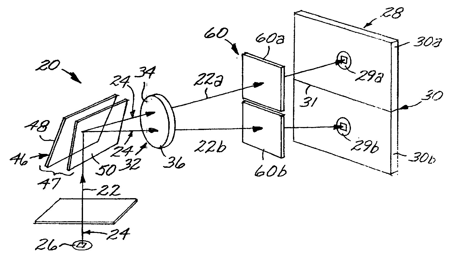
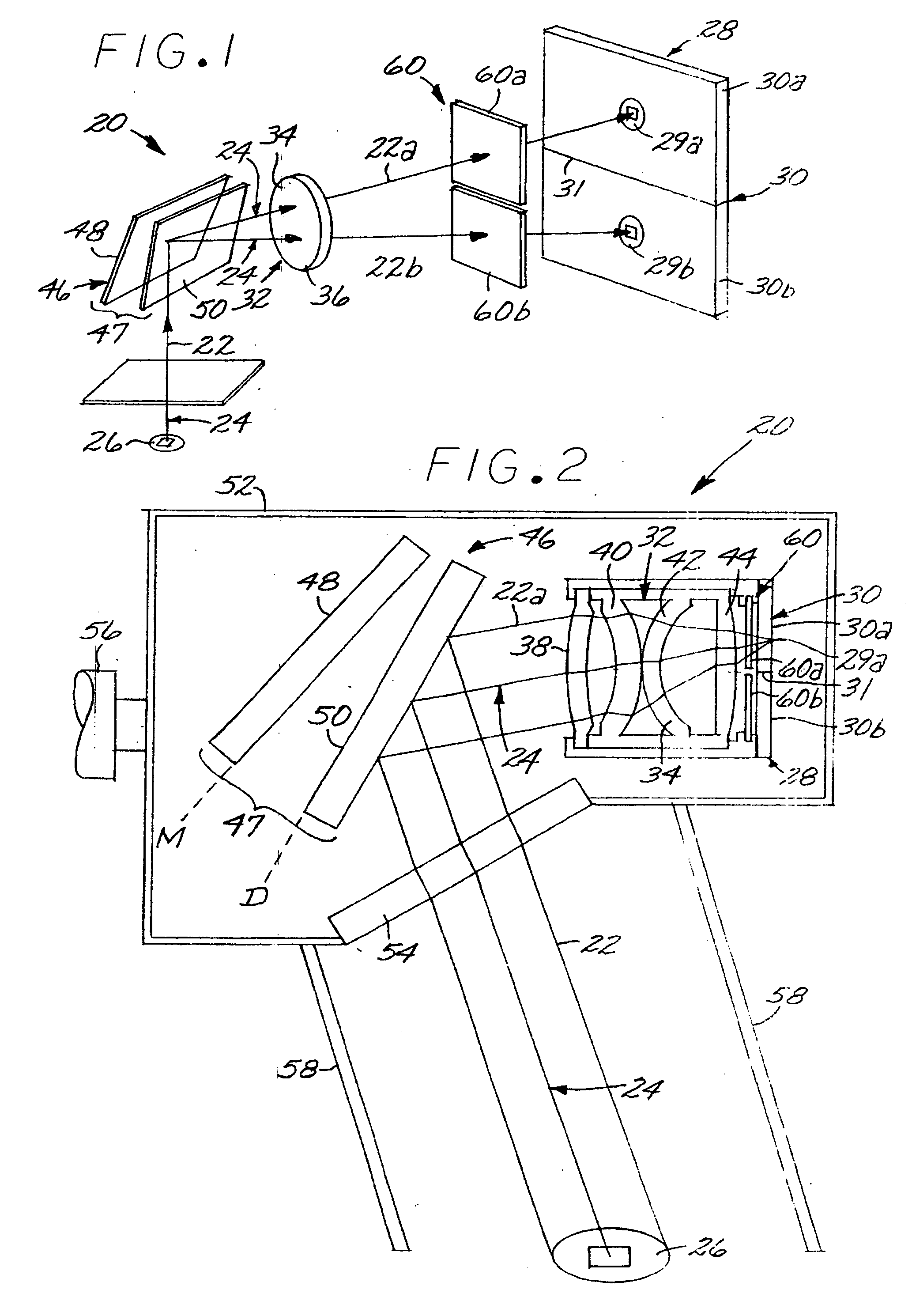
[0022]FIGS. 1-3 schematically depict an imaging sensor system 20 that images a light beam 22 traveling in two (or more) different spectral bands λ1 and λ2 on a light path 24 from a target 26. The “spectral bands”λ1 and λ2 may each refer to a single discrete wavelength or to a range of wavelengths, and there may be other wavelengths present in the light beam 22 as well. The spectral bands λ1 and λ2 may be in any range, such as the ultraviolet, visible, or infrared, but are preferably in the infrared for the applications of most interest.

[0023] The sensor system 20 includes an imaging sensor 28 operable to image respective light subbeams 22a and 22b of the respective different spectral bands λ1 and λ2. The imaging sensor 28 preferably includes at least one focal plane array 30, and preferably exactly one focal plane array 30. If exactly one focal plane array 30 is used, that focal plane array 30 must be capable of imaging light of both spectral bands λ1, and λ2. The use of exactly on...


PUM


Abstract

An imaging sensor system images in two different spectral bands a light beam traveling on a light path from a target. The sensor system includes an imaging sensor operable to image light of the two different spectral bands, a common optics having at least one reflective or refractive optical element, and a wavelength-selective beamsplitter on the light path between the target and the imaging sensor. The wavelength-selective beamsplitter splits the light beam into two subbeams, one subbeam for each of the two different spectral bands, that are respectively incident upon two different locations of the imaging sensor. The imaging sensor may be used to detect buried explosive mines.

Description

[0001] This application claims the benefit of U.S. Provisional Application No. 60 / 551,737, filed Mar. 10, 2004, the disclosure of which is hereby incorporated herein by reference.[0002] This invention relates to an imaging sensor system and, more particularly, to an imaging sensor system that images in two or more spectral bands. BACKGROUND OF THE INVENTION [0003] An imaging sensor system forms an image of a target on an imaging sensor. The imaging sensor converts the incident light image to electrical or optical signals for further processing such as pattern recognition functions. The imaging sensor system is distinct from a non-imaging sensor system, which reacts to the presence of the target but does not form an image of the target. [0004] One potential application of imaging sensor systems is the detection of buried anti-personnel or anti-vehicle explosive mines. Such explosive mines, if undetected, may pose a hazard long after an area is otherwise thought to be safe for use. On...

Claims


Application Information

Patent Timeline
IPC IPC(8): G01V8/10G02B23/12G02B27/14H04N5/225H04N5/33
CPCG02B23/12H04N5/2254G02B27/148G02B27/1013G01J3/021G01J3/36
Inventor CHEN, CHUNGTE W.TSAI, CHENG-CHIHANDERSON, JOHN S.
Owner OL SECURITY LIABILITY CO
Why Eureka
Try Eureka