Optical pickup apparatus and an optical disc drive apparatus equipped with such an optical pickup

a technology of optical disc drive and optical pickup, which is applied in the field of optical disc drive apparatuses, can solve the problems of increasing the size affecting the operation of the optical system, and acquiring a high output of light sources, so as to achieve good light use efficiency, no chromatic aberration, and the effect of chromatic aberration

Inactive Publication Date: 2005-09-15
RICOH KK
View PDF16 Cites 18 Cited by
  • Summary
  • Abstract
  • Description
  • Claims
  • Application Information

AI Technical Summary

Benefits of technology

[0060] The optical pickup apparatus according to the above-mentioned invention may further comprise an aspheric aberration detecting means for detecting an aspheric aberration in a reflected light from one of the recording surfaces of one of the optical information recording media onto which a light beam from at least one of the light sources is converged. Accordingly, a chromatic aberration can be corrected even when a refraction lens is used for the objective lens. Thus, an optical system having a good light use efficiency and no chromatic aberration can be realize, and it is possible to achieve high speed and high stabilization. Moreover, it also becomes possible to reduce a chromatic aberration generated due to a short time wavelength fluctuation with respect to the optical system of each light source. Accordingly, since the direction of movement and the amount of movement of the coupling lens can be recognized instantaneously by the spherical aberration detection signal, there is no need to seek for an optimum position. Thus, a spherical aberration and a chromatic aberration can always be corrected for any cause, thereby enabling a high speed and excellent recording and reproduction.
[0061] In the optical pickup apparatus according to the above-mentioned invention, one group of lenses located closest to the light sources may serve as a concave lens. Accordingly, since a rim light intensity (RIM) of a light beam incident on the objective lens can be increased by making a lens closer to a light source than the optical path synthesizing and separating mechanism as a concave lens so as to increase a diverging angle of a diverging light from the light source concerned, a beam spot diameter on a disc is decreased, which results an improvement in the recording and reproducing performance. Moreover, by combining with a convex lens closer to the objective lens than the optical path synthesizing and separating mechanism, an achromatic design can be made even if it is a single lens.
[0062] In the above-mentioned optical pickup apparatus, λA<λB may be satisfied where λA is a wavelength of a light beam that transmits the concave lens, and λB is a wavelength of a light beam that does not transmit the concave lens. Accordingly, if the light source on the side of the concave lens is set to one having a shorter wavelength than the other light source, an effect of increasing the RIM becomes more remarkable due to a divergence action of the concave lens.
[0063] In the optical pickup apparatus according to the above-mentioned invention, one group of lenses located closest to the light sources may serve as a convex lens. Accordingly, by making the group of lenses of the coupling lens on the side of the objective lens as a convex lens, an optical path for coupling can be reduced, which miniaturizes the optical pickup apparatus. Additionally, since a light beam of the light source closest to the convex lens is coupled up to a smaller RIM, the coupling efficiency and a power on the disc surface are increased, which realizes high-speed recording.
[0064] In the above-mentioned optical pickup apparatus, λB<λA may be satisfied where λA is a wavelength of a light beam that transmits the convex lens, and λB is a wavelength of a light beam that does not transmit the convex lens. Accordingly, if the light source on the side of the convex lens is set to one having a longer wavelength than the other light source, the above-mentioned effect can be more remarkable due to a convergence action of the convex lens.
[0065] In the optical pickup apparatus according to the present invention, the at least one group of lenses moved by the lens moving mechanism in the direction of the optical axis may be located between the light sources and the optical path synthesizing and separating component. Accordingly, since a degree of divergence can be changed only for a light beam of a light source that require an adjustment, other light sources can always be fixed in positions, which provides a stable performance.

Problems solved by technology

Moreover, with an increase in the recording capacity, there is a strong demand for improvement in the recording or reproducing speed, and acquisition of a high output of a light source and also a high efficiency of the optical system has become a important issue.
If a focal distance of the coupling lens 310 is set to f1, and a focal distance of the coupling lens 320 is se to f2, an optical path length of equal to or longer than f1 or f2, must be provided before incident on the beam splitter 321, which causes a problem that the optical system is increased in its size.
Moreover, if the coupling lenses 310 and 320 are made common, a coupling efficiency of one of the light sources is decreased, which causes a problem in that a spot power on the discs 315a and 315b is decreased.
Although the spot diameter decreases as the RIM increases, a coupling efficiency of effectively converging the light beam from the light source on a surface of the disc is decreased, which causes a problem in that a power is not sufficient and a recording and reproducing speed is decreased.
Further, a combination of different numerical apertures causes a problem that the above-mentioned problems become severer.
However, with respect to the coupling lens, in order to optimize the coupling efficiency of each light source, it is necessary to use lenses having different distance for each light source since the numerical aperture and the light taking angle of the light beam differ for each light source, and, thereby, it is difficult to make the coupling lens common to a plurality of light sources.
Moreover, when performing recording or reproduction on a multi-layer optical disc, a spherical aberration is generated due to variation in the thickness of layers, which causes a signal degradation due to enlargement of a converged light spot.
The technique disclosed in the above-mentioned patent document 1 is not applicable to a structure in which two light sources are located close to each other and mounted in one package.
Additionally, there is a problem in that a chromatic aberration and a spherical aberration generated by a fluctuation in the wavelength of the light source and a variation in a substrate thickness of a multi-layer disc and a disc cannot be corrected.
Additionally, the technique disclosed in the above-mentioned patent document 2 has a problem in that only one light source is used and it is difficult to provide a plurality of optical information recording media.
Moreover, in the above-mentioned patent document 2, there is a problem in that it is difficult to handle a plurality of optical information recording media since there is provided only one light source.
However, there still is a problem in that a correction of a chromatic aberration and a spherical aberration due to a variation in a substrate thickness of a disc, a multi-layer disc or a fluctuation in a wavelength cannot be achieved, which correction is needed with reduction in the wavelength and increase in numerical aperture.
However, such a method may increase a number of component parts, which increases the size of the entire apparatus.
Additionally, there is a problem in that a spot power on a disc surface is decreased due to a decrease in a transmittance of a light beam, which may cause difficulty in achieving high-speed recording.
However, there is a problem, in this structure, that the optical pickup of this structure is not suitable for an optical disc drive, which requires miniaturization, since a number of lenses located in the optical system is large.
In the above-mentioned patent document 5, there is a problem in that it is difficult to achieve a correction of a spherical aberration since the magnification change of the coupling lens is large and a drive amount (distance of movement) must be very small.

Method used


Image

  • Optical pickup apparatus and an optical disc drive apparatus equipped with such an optical pickup
  • Optical pickup apparatus and an optical disc drive apparatus equipped with such an optical pickup
  • Optical pickup apparatus and an optical disc drive apparatus equipped with such an optical pickup

Examples


first embodiment

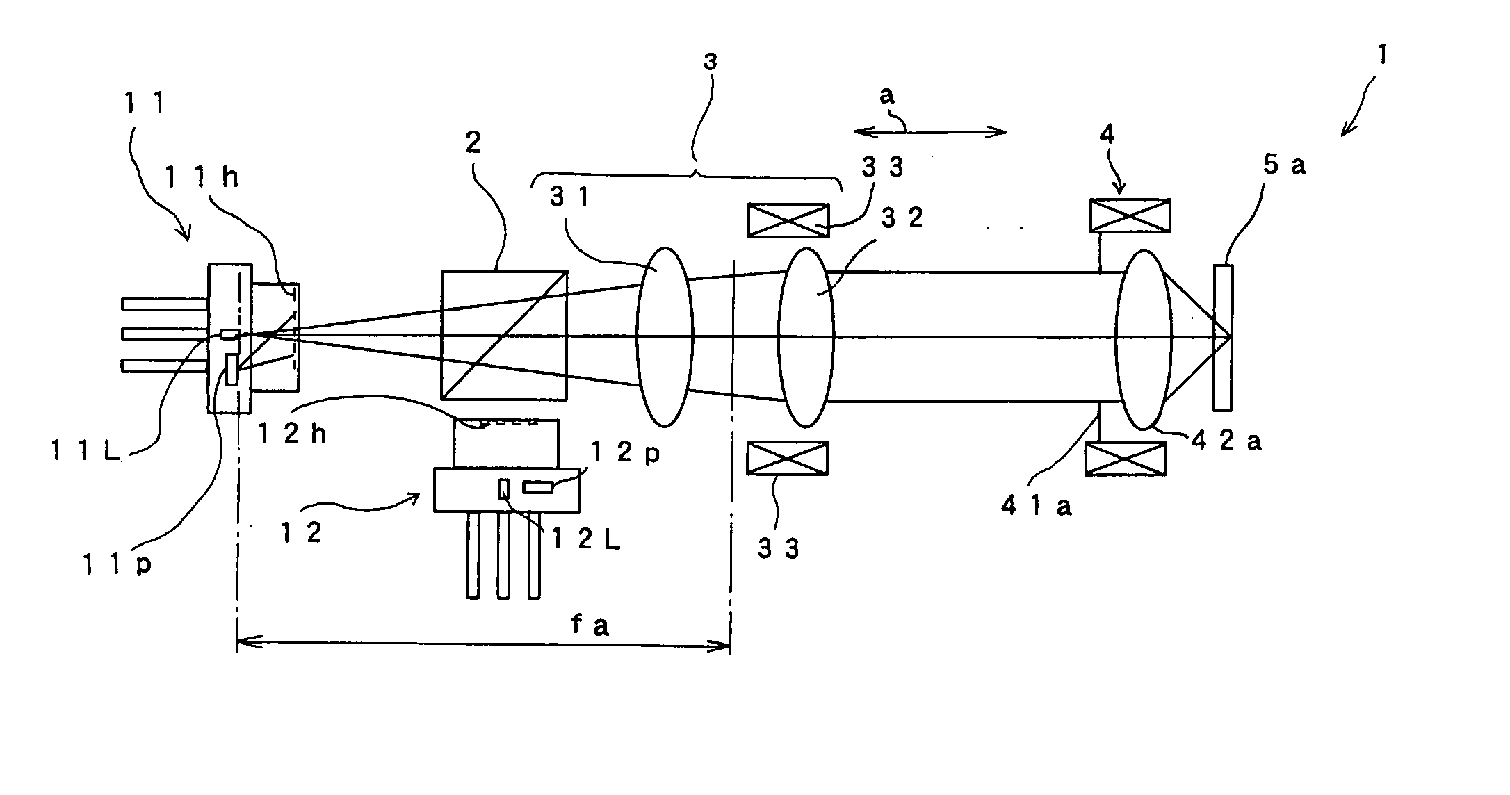
[0096] A description will be given of an optical pickup apparatus according to a first embodiment of the present invention. FIGS. 5A and 5B show an optical system provided in the optical pickup apparatus according to the present invention.

[0097] The optical system 1 shown in FIGS. 5A and 5B comprises a first hologram unit 11, a beam splitter 2, a coupling lens system 3 and an actuator 4 that are arranged on a straight line in that order. The optical system 1 also comprises a second hologram unit 12, which faces the beam splitter 2 and has an optical axis perpendicular to the straight line. It should be noted that the first coupling lens system 3 includes a first coupling lens (a group of lenses) 31, a second coupling lens (a group of lenses) 32, a single-axis actuator 33 for driving the second coupling lens 32 in a direction of the optical axis, etc. The actuator 4 is provided with apertures (opening parts) 41a and 41b, objective lenses 42a and 42b, a holder 43, etc., so as to driv...

second embodiment

[0150] A description will now be given of a second embodiment of the present invention. It should be noted that parts that are equivalent to the parts described in the above description are given the same reference numerals, and descriptions there of may be omitted.

[0151] A light beam projected from a semiconductor laser is a radially expanding light beam, and a beam diameter parallel to the junction plane of the semiconductor laser is different from a beam diameter of perpendicular to the junction plane. For this reason, in an optical pickup apparatus, generally, the beam diameters in all directions are equalized by using a beam shaping prism so as to equalize a rim intensity of the light beam incident on an objective lens having a circular aperture, thereby suppressing reduction in an amount of light.

[0152] However, a beam shaping prism cannot be provided in an optical system using a CL expander since an optical path is a diverging / converging optical path. For this reason, in or...


PUM

PropertyMeasurementUnit
wavelengthaaaaaaaaaa

Abstract

An optical pickup apparatus couples light beams, and corrects a chromatic aberration and a spherical aberration. A coupling lens includes groups of lenses common to the light sources so as to converge a light beam from each of the light sources. An aperture changes an aperture diameter for the light beam, which has been converged by the coupling lens, in accordance with one of the light sources from which the light beam is emitted. An objective lens converges the light beam onto a recording surface of one of the optical information recording media corresponding to the one of the light sources that emits the light beam. A lens moving mechanism moves at least one group of lenses from among the groups of lenses of the coupling lens in a direction of an optical axis thereof in accordance with an aperture diameter of the aperture.

Description

BACKGROUND OF THE INVENTION [0001] 1. Field of the Invention [0002] The present invention generally relates to optical disc drive apparatuses and, more particularly, to an optical pickup apparatus for recording or reproducing information on or from an optical information recording medium by converging a light beam on a recording surface of the optical information recording medium and an optical disc drive apparatus equipped with such an optical pickup apparatus. [0003] 2. Description of the Related Art [0004] In recent years, a demand for high-recording density and a large capacity optical disc has been increasing. In order to increase a recording density, it is effective to increase a numerical aperture (NA) of an objective lens and reduce a wavelength of a light to be used so as to reduce a sot diameter of the light converged by the objective lens. [0005] Moreover, with an increase in the recording capacity, there is a strong demand for improvement in the recording or reproducing ...

Claims


Application Information

Patent Timeline
Patent Type & Authority Applications(United States)
IPC IPC(8): G11B7/00G11B7/12G11B7/125G11B7/135
CPCG11B7/123G11B7/1275G11B7/1376G11B2007/0013G11B7/13927G11B2007/0006G11B7/139
Inventor KITABAYASHI, JUNICHIOGATA, TETSUYA
Owner RICOH KK
Why Eureka
Try Eureka