Device and method for measuring cardiac function

a technology for cardiac function and measuring devices, applied in the field of measuring devices and methods related to cardiac function, can solve the problems of inconvenient and non-continuous methods, invasive and non-continuous methods, and the method requires expert medical attention

Pending Publication Date: 2005-09-15
IMPEDANCE VASCULAR IMAGING PROD
View PDF25 Cites 22 Cited by
  • Summary
  • Abstract
  • Description
  • Claims
  • Application Information

AI Technical Summary

Benefits of technology

[0021] One aspect of the present invention is a device for determining at least a left ventricular end diastolic volume LVEDV for a heartbeat of a beating heart of a mammal, in particular a human being, having a body having a thorax. The device comprises a current source for producing an alternating current with a frequency, one or more upper supply electrodes and one or more lower supply electrodes, which can be applied to the body of the mammal and which can be connected to the current source, for supplying the alternating current to the body,

Problems solved by technology

Furthermore, the diluted fluid is measured only during the first five or six seconds after the beat, after which the rest of the curve is extrapolated, which may lead to errors.
Moreover, it is an invasive and non-continuous method, with relatively high risk and discomfort for the patient.
Furthermore, this method requires expert medical attention.
Hence, this is also an invasive method, which is very risky and bothersome for the patient, is laborious and costly and is furthermore rather inaccurate because relatively crude geometrical models must be used to calculate the quantities.
All these methods have the inherent error of inclusing the isovolumetric period.
This method had the above-mentioned advantages, but it showed some inaccuracy when compared to the standard thermodilution method.
In part this was caused by the rather crude model that was used, e.g. for the thorax.
This makes comparison even more difficult.
Furthermore, it could not determine ejection fraction nor LVEDV.
Furthermore, the formula for determining EF was found to be inaccurate (standard error=11%) and not to give very useful results.

Method used


Image

  • Device and method for measuring cardiac function
  • Device and method for measuring cardiac function
  • Device and method for measuring cardiac function

Examples


Embodiment Construction

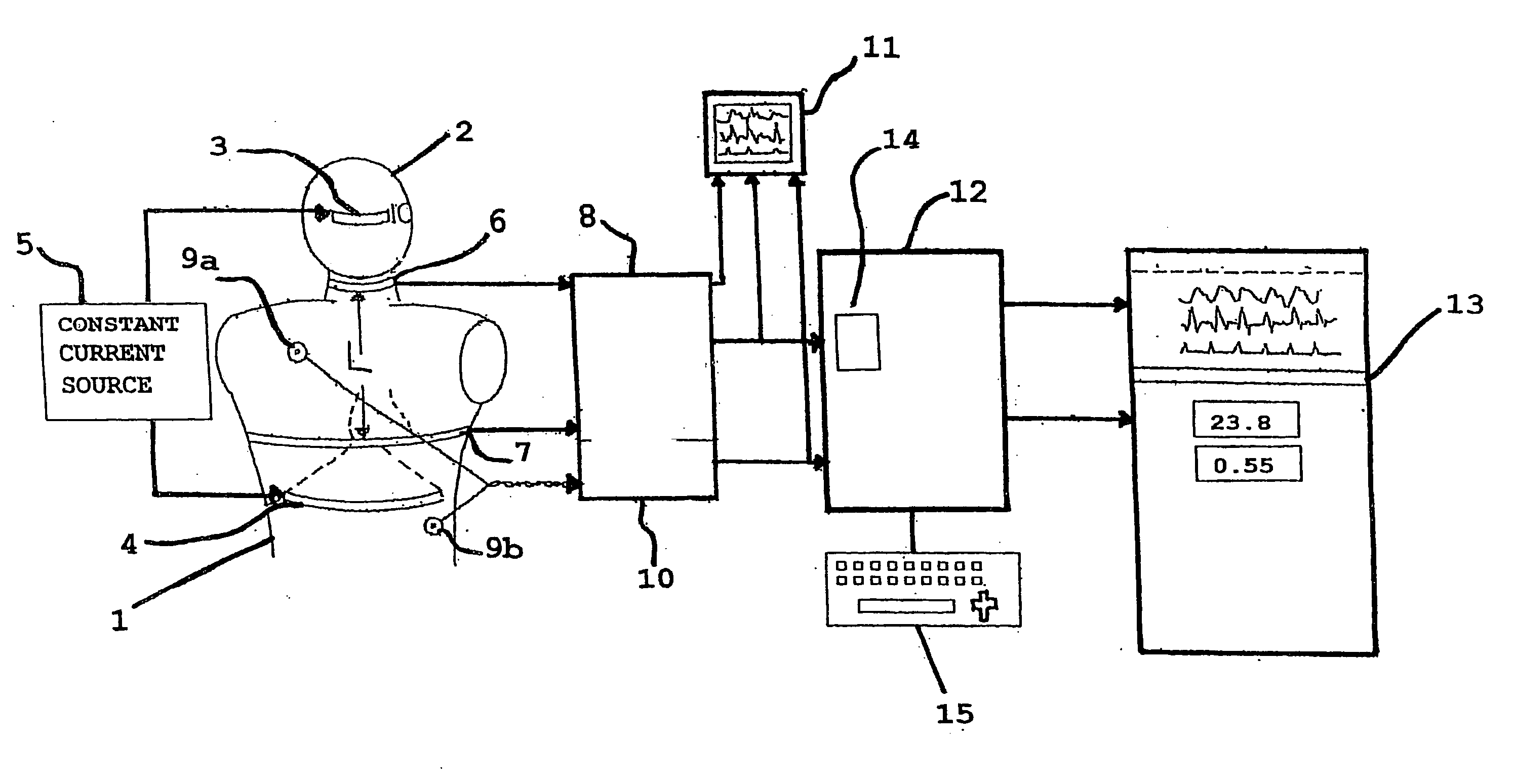
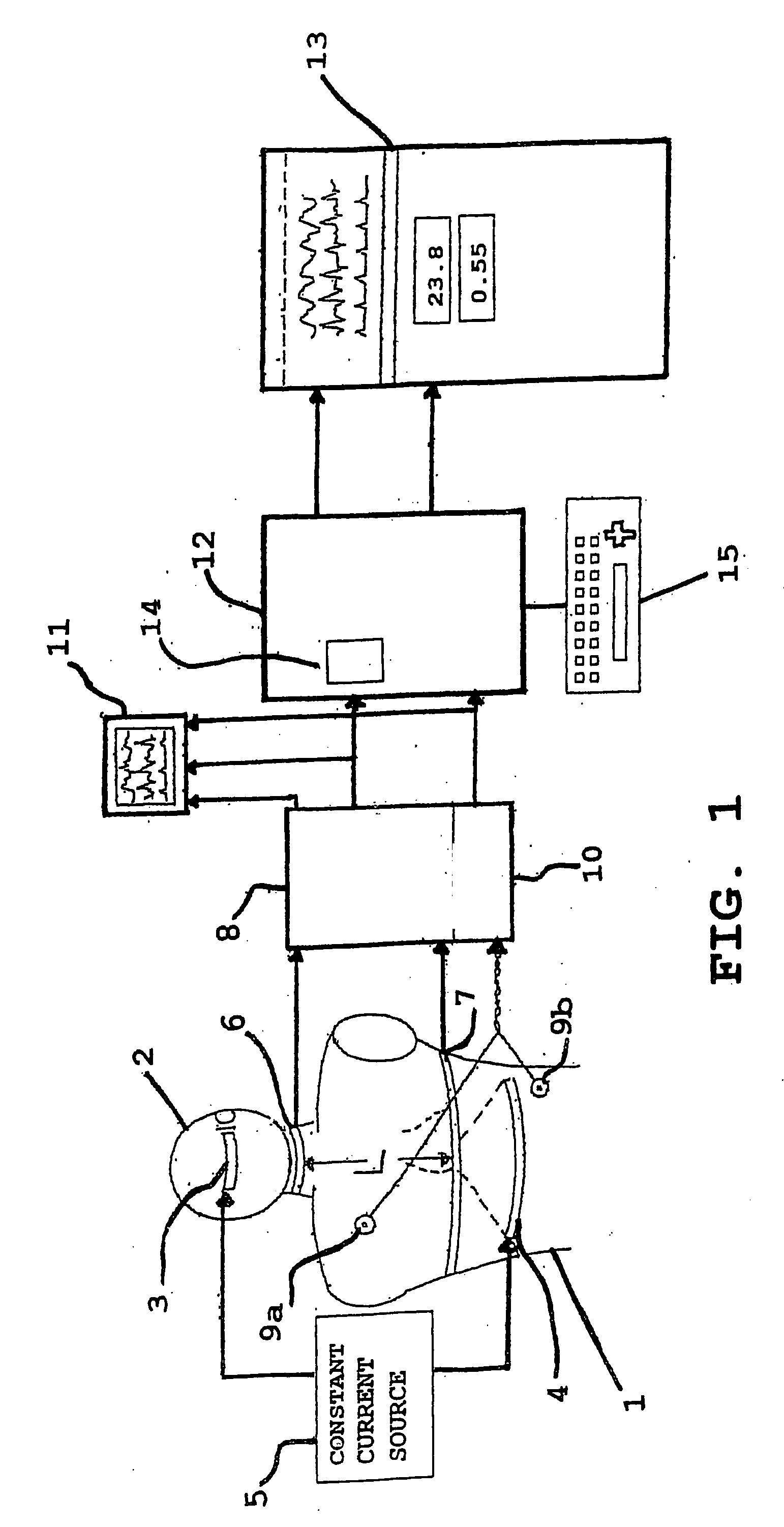
[0053] In FIG. 1 there is shown diagrammatically the upper part 1 of the body of a human being, including the head 2.

[0054] One or more upper supply electrodes 3 are applied to the forehead, and one or more lower supply electrodes 4 are supplied to the upper part 2 of the body at waist level. A current source 5 is connected to both the upper supply electrodes 3 and the lower supply electrodes 4.

[0055] One or more upper measuring electrodes 6 are applied to the body at the midneck region, and one or more lower measuring electrodes 7 are applied at the height of the xiphoid junction of the sternum. The upper 6 and lower measuring electrodes 7 are connected to a measuring device 8.

[0056] Furthermore, first 9a and second 9b EKG-electrodes are applied to the body, and are connected to an EKG-measuring means 10.

[0057] Both the measuring means 8 and the EKG-measuring means 10 are connected to a display 11 and to a processing unit 12. In its turn, the processing unit 12 is connected to ...


PUM


Abstract

A device and method for determining at least the left ventricular end diastolic volume LVEDV of a beating heart of in particular a human being, is disclosed, the device comprising a current source supply electrodes, for supplying alternating current to the body, measuring electrodes, for receiving an impedance signal, measuring means, for measuring said impedance signal, a processing unit, for processing and outputting the value of said impedance signal and the first time derivative thereof, and means for determining the duration DFT of a heartbeat, and wherein the processing unit is designed for determining and outputting the value of LVEDV in dependence of both said duration DFT and said impedance and the change of the first time derivative of said impedance during the pre-ejection period.

Description

FIELD OF THE INVENTION [0001] The present invention generally relates to a device and method for measuring quantities related to cardiac function. More particularly, the present invention is directed to the use of a bioimpedance device and method to determine non-invasively and on a beat-to-beat basis the left ventricular end diastolic volume and other quantities of the animal or human heart. BACKGROUND OF THE INVENTION [0002] Cardiac monitoring is the measuring of various quantities related to the functioning of the human or animal heart. Some of the measured quantities are heart rate (HR), stroke volume (SV), cardiac output (CO=HR×SV), etc. A number of other quantities, which are used in this application, are to be understood as follows: [0003] left ventricular end diastolic volume (LVEDV): the maximum volume of the left ventricle, just before the contraction of the heart. [0004] left ventricular end systolic volume (LVESV): the minimum volume of the left ventricle, at the end of ...

Claims


Application Information

Patent Timeline
Patent Type & Authority Applications(United States)
IPC IPC(8): A61B5/04A61B5/0402A61B5/053A61B7/04
CPCA61B5/0402A61B5/7239A61B7/04A61B5/0535A61B5/318
Inventor JUDY, WILLIAM V.
Owner IMPEDANCE VASCULAR IMAGING PROD
Why Eureka
Try Eureka