Method for manufacturing optical fiber

a manufacturing method and optical fiber technology, applied in the direction of glass making apparatus, manufacturing tools, instruments, etc., can solve the problems of increasing the risk of preform damage by accident, contaminated preform, unstable drawing condition, etc., and achieve the effect of reducing pressur

Inactive Publication Date: 2005-09-22
FURUKAWA ELECTRIC CO LTD
View PDF4 Cites 75 Cited by
  • Summary
  • Abstract
  • Description
  • Claims
  • Application Information

AI Technical Summary

Benefits of technology

[0044] A thirty-first embodiment of the method of the present invention for manufacturing an optical fiber is characterized by that wherein the spacer has a circular cross-section with a first hole at the center and a lot of second small holes, wherein outer diameter of the spacer is selected to fit to the inn

Problems solved by technology

However, immediately after the onset of drawing, the tip shape of the preform is different from the stable one described above, and the drawing condition is unstable.
Moreover, introduction of an additional step may increase the risk of the preform being damaged by accident.
Furthermore, introduction of an additional step may increase the risk of a preform being contaminated, which may lead to the reduced strength of the fiber obtained therefrom.
As preforms become large, machines responsible for their processing must be large, and then workability is impaired, and cost required for the installment and running of the machines increases.
This may result in the reduced strength of the optical fiber because, if the fiber is exposed to an external force, stresses will concentrate on this soiled spot.
Since the central cavity of a jacketing tube is comparatively inaccessible to water even when the jacketing tube is rinsed with water, the detergent solution soaking i

Method used


Image

  • Method for manufacturing optical fiber
  • Method for manufacturing optical fiber
  • Method for manufacturing optical fiber

Examples


example 1

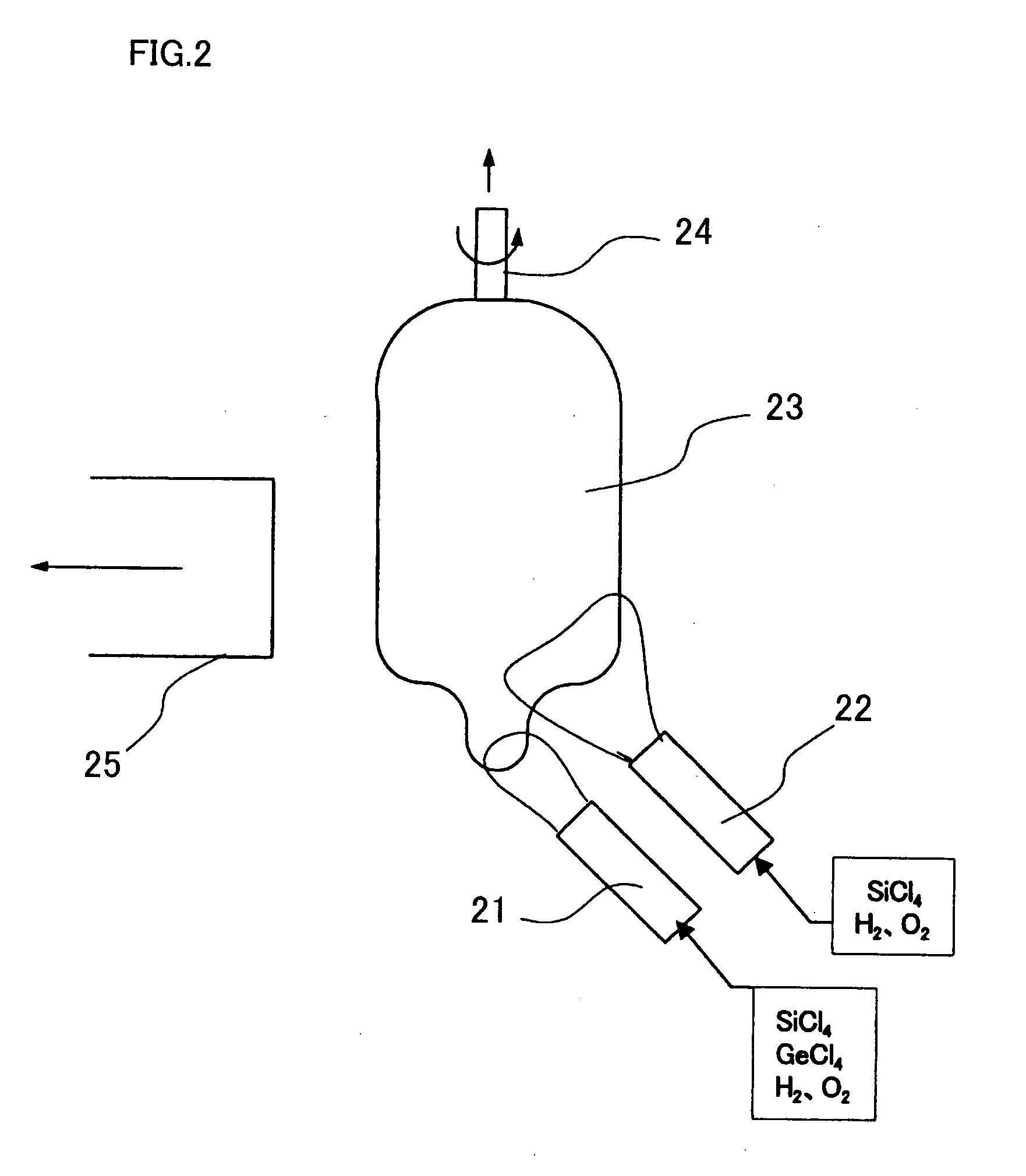
[0175] As shown in FIG. 2, VAD consists of discharging vaporized silicon tetrachloride and germanium tetrachloride together with oxygen and hydrogen via a core-preparing burner 21 consisting of a multiple pipe structure, igniting the gas mixture to burn to allow thereby a hydrolysis reaction to occur in the resulting flame, producing particulate synthetic silica glass, and depositing the particles onto a seed rod 24 to obtain a porous core soot 23. To obtain a preform stable in characteristics, an additional burner 22 is provided above the core burner 21 which discharges silicon tetrachloride and oxygen / hydrogen to allow the gas mixture to react, and deposit the particulate synthetic silica glass onto the core soot to provide a part of the cladding layer around it. The particulate synthetic silica glass is heated to around 1500 to 1600° C. to produce a transparent glass body. With regard to a single-mode optical fiber, its core / cladding ratio is about 1:13. It is difficult according...

example 2

[0184] As in Example 1, a supporting tube 83 was attached by welding to an inert end of a jacketing tube 82 whose drawn end has been tapered, and the jacketing tube 82 was attached to a processing lathe by means of the supporting tube 83 whose distal end is held by a chuck of the lathe as shown in FIG. 8A. To a drawn end of a core-rod 81 which was processed in advance to have a specified dimension, a supporting rod 84 was attached as in Example 1, and the core-rod 81 was similarly attached to the lathe. The core-rod 81 was then inserted into the jacketing tube 82. The chucks of the lathe were rotated as in Example 1, and the tip of the glass assembly was exposed to oxygen / hydrogen flame of the burner so that the drawn ends of the jacketing tube 82 and core-rod 81 were melted to be sealed. Then, a glass assembly incorporating the core-rod and jacketing tube whose tip was collapsed as shown in FIG. 8B was obtained. The glass assembly was then transferred to a fiber-drawing equipment w...

example 3

[0185] According to the method of Example 2, as shown in FIG. 29, a drawn end of a jacketing tube 82 has a straight inner surface while a drawn end of a core-rod 81 has a taper when the two ends are welded together just before the onset of fiber-drawing. Therefore, if the core-rod 81 and jacketing tube 82 are displaced longitudinally with respect to each other, the two drawn ends could not be successfully welded, because then the clearance between the two ends may be too large. To meet such situation, as shown in FIG. 9, a rod was prepared which had, on one end, a recess whose surface had a tapered profile, and this was called a jacketing tube sealing rod 95. Then, the rod 95 was placed with respect to the glass assembly such that the recess was positioned practically at the same level with the drawn ends of the core-rod 81 and jacketing tube 82 in a longitudinal direction. Except for this, the glass assembly was treated as in Example 2 to produce a preform of an optical fiber. FIG....


PUM

PropertyMeasurementUnit
Fractionaaaaaaaaaa
Currentaaaaaaaaaa
Nanoscale particle sizeaaaaaaaaaa

Abstract

A method of manufacturing an optical fiber, characterized by comprising the steps of forming a glass body having a core, forming a glass tube constituting a clad portion, inserting the glass body into the glass tube, forming the glass body integrally with the glass tube, finishing at least the extraction side end part of the glass tube in a tapered shape and washing the outer surface of the glass tube, characterized in that a difference between the outer diameter of the glass body and the inner diameter of the glass tube is 1.0 to 10.0 mm, and the inner diameter of a support tube fitted to one end of the glass tube is increased more than that of the glass tube or the extraction side end part of the glass tube is sealed with a tapered part provided at least on the inner surface thereof and a spacer is installed so that a clearance between the outer diameter of the glass body and the inner diameter of the glass tube becomes generally constant in the longitudinal direction.

Description

TECHNICAL FIELD [0001] The present invention relates to the method for manufacturing an optical fiber, more specifically to the method for manufacturing an optical fiber for telecommunication. RELATED ART [0002] Silica glass is used as the base material of an optical fiber. Generally, method for manufacturing an optical fiber proceeds as follows: a preform having a predetermined refractive index profile is synthesized; it is melted and softened in a heating furnace; and it is pulled to be a thin fiber. The proposed preform synthesizing methods include MCVD method, VAD method, OVD method and so on. [0003] For example, according to a known method for preparing a preform shown in FIG. 6A, a glass body including a core which will form a central portion of an optical fiber (which may be called a core-rod hereinafter) is manufactured by one of the above methods (VAD method in the particular embodiment shown in FIG. 6) to produce a core-rod 61, and a jacketing tube 62 made of silica glass ...

Claims


Application Information

Patent Timeline
IPC IPC(8): C03B37/012C03B37/027
CPCC03B37/01211C03B37/02754C03B37/0126C03B37/01245Y02P40/57
Inventor MORIDAIRA, HIDEYAUEHARA, MASAMITSUKAMIYA, TAMOTSU
Owner FURUKAWA ELECTRIC CO LTD
Why Eureka
Try Eureka