Imaging device with multiple fields of view incorporating memory-based temperature compensation of an uncooled focal plane array

Inactive Publication Date: 2005-09-22
APROLASE DEV
View PDF10 Cites 199 Cited by
  • Summary
  • Abstract
  • Description
  • Claims
  • Application Information

AI Technical Summary

Benefits of technology

[0013] One benefit of the invention is that imagery generated from an focal plane array, whose response varies non-uniformly with temperature will be consistent even as the ambient temperature varies. The illustrated embodiment explicitly contemplates a long wave infrared (LWIR) microbolometer focal plane array typically operating in the range of 8-14.mu.m and a short wave infrared (SWIR) InGaAs focal plane array typically operating in the range of 0.7-1.5.mu.m such as Sensors Unlimited, Inc.'s model number SU320-1.7T1. However, any focal plane array now known or later devised may benefit from application of the present invention. This approach for compensating for ambient temperature variation will significantly reduce the power as compared to the traditional approach based on using a thermoelectric cooler to regulate the temperature of the focal plane array or using a processor to calculate the values in real ti

Problems solved by technology

While there is a potential of using an uncooled microbolometer focal plane array without a thermoelectric cooler, the difficulty is that calculating the conversion between the measured voltage to a pe

Method used


Image

  • Imaging device with multiple fields of view incorporating memory-based temperature compensation of an uncooled focal plane array
  • Imaging device with multiple fields of view incorporating memory-based temperature compensation of an uncooled focal plane array
  • Imaging device with multiple fields of view incorporating memory-based temperature compensation of an uncooled focal plane array

Examples


Embodiment Construction

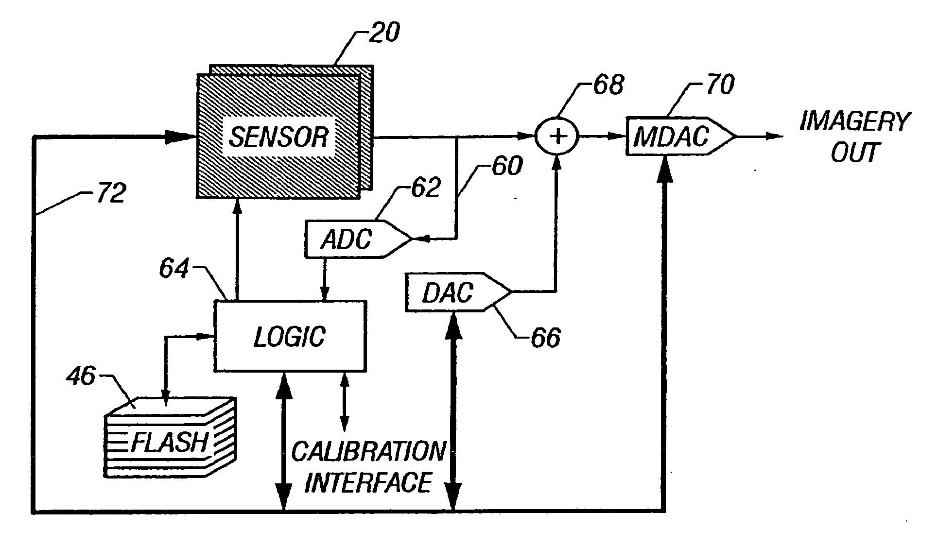
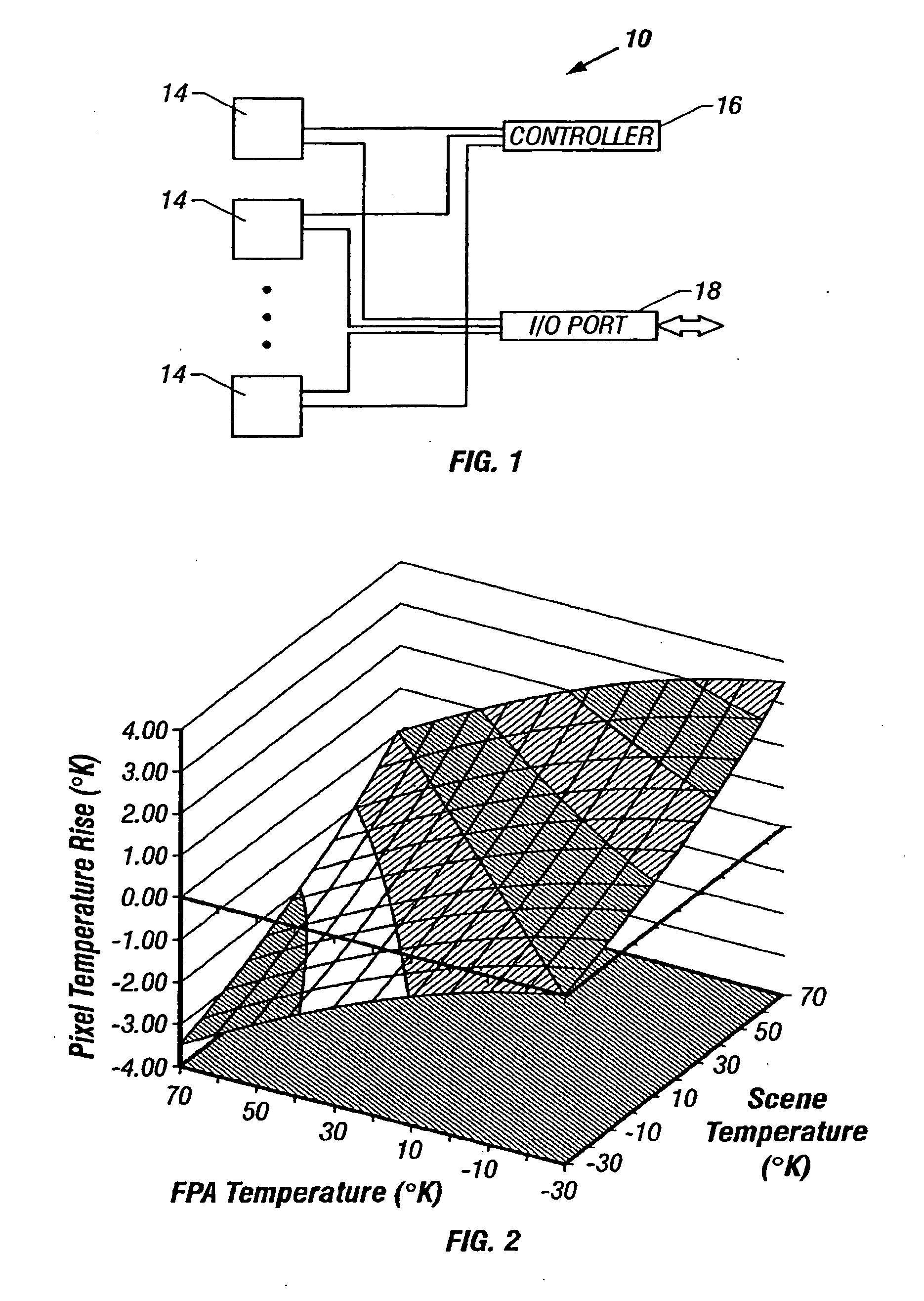
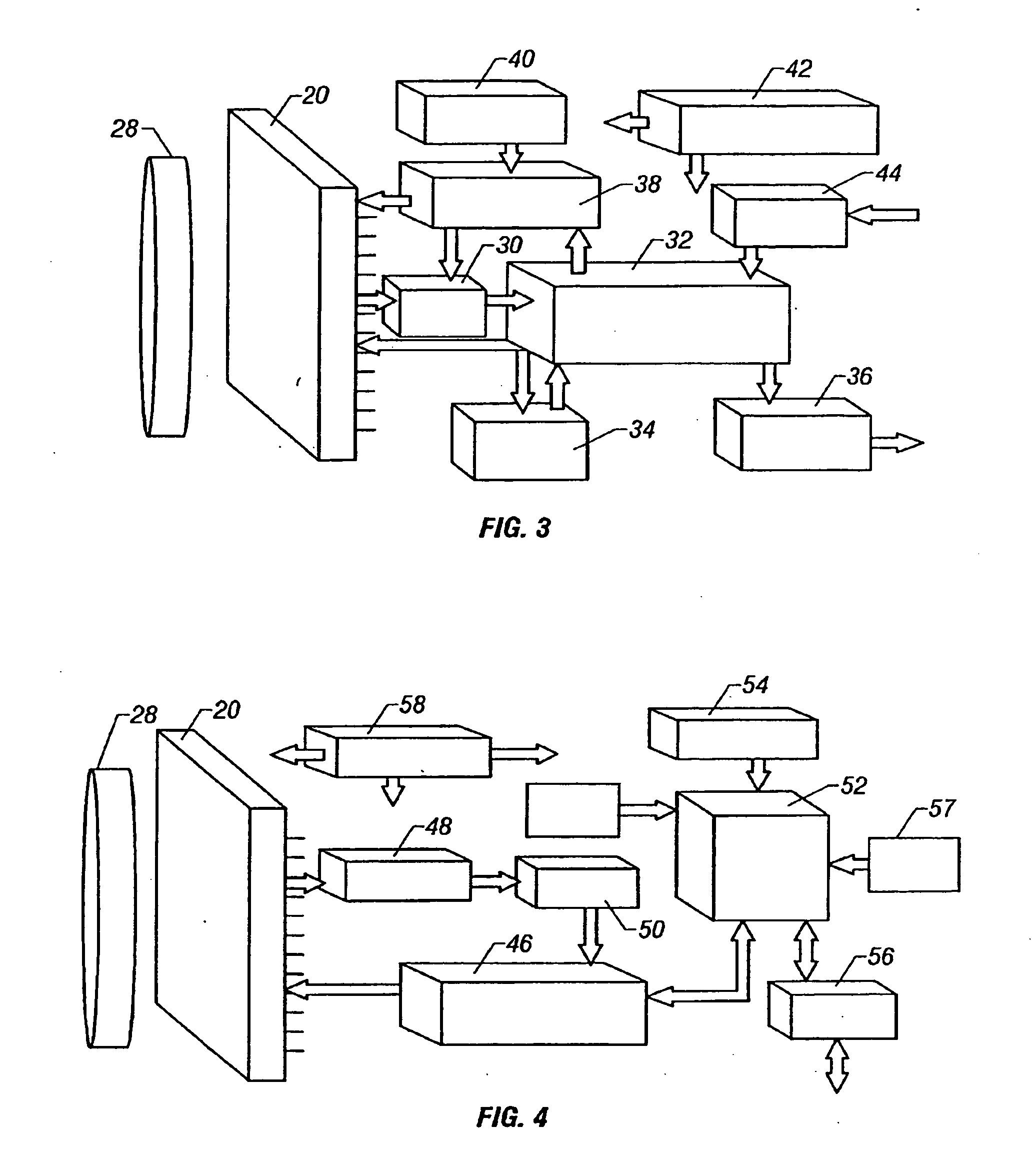
[0032] The invention is directed to a low power infrared (IR) camera that operates without a temperature stabilization system or real time calculation of detector coefficients. What will be described is an illustrated embodiment in which the invention is employed, namely a camera system 10. The invention is expressly not limited to the illustrated embodiment and may be equally applied to many other systems which are quite different in nature. Therefore, before considering the invention briefly summarized above, consider one environment or illustrated embodiment in which it may be used to advantage.

[0033] In the illustrated embodiment the invention is incorporated into an ultra compact camera system 10 manufactured by Irvine Sensors, Costa Mesa, Calif. This embodiment utilizes a microbolometer imaging array 20, namely model Gen-4, 320.times.240 UFPA, manufactured by Boeing Aircraft, Seattle, Wash. Again any focal plane array could be substituted. The infrared (IR) based camera syste...


PUM


Abstract

A plurality of temperature dependent focal plane arrays operate without a temperature stabilization cooler and/or heater over a wide range of ambient temperatures. Gain, offset and/or bias correction tables are provided in a flash memory in memory pages indexed by the measured temperature of the focal plane arrays. The memory stores a calibration database, which is accessed using a logic circuit which generates a memory page address from a digitized temperature measurement of each of the focal plane array. The calibration database is comprised of an array of bias, gain and offset values for each pixel in the focal plane array for each potential operating temperature over the entire range of potential operating temperatures. The bias, gain and offset data within the database are read out, converted to analog form, and used by analog circuits to correct the focal plane array response. The output of each of the FPAs is multiplexed to a shared processing module and calibration data for each of the FPAs is accessed from the shared processing module.

Description

REFERENCE TO RELATED APPLICATIONS [0001] This application is a continuation in part of U.S. patent application Ser. No. 10 / 281,393, filed Oct. 25, 2002, now allowed, which in turn, is continuation in part of U.S. patent application Ser. No. 09 / 853,819, filed on May 11, 2001, now U.S. Pat. No. 6,476,392. BACKGROUND OF THE INVENTION [0002] 1. Field of the Invention [0003] The invention relates to infrared instruments and cameras and in particular to calibration of the same. [0004] 2. Description of the Prior Art [0005] Recent advances in infrared (IR) detector technology have led to the commercially availability of new detector technologies that do not require cryogenic cooling. These new detector technologies include ferroelectric and microbolometer technologies. The currently commercially available microbolometer detector arrays are based on a technology that was originally developed by Honeywell Sensor & System Development Center and was licensed to Boeing (formerly Rockwell), Rayt...

Claims


Application Information

Patent Timeline
IPC IPC(8): G01J5/20G01J5/22H01L25/00H04N5/217H04N5/33
CPCG01J5/22H04N5/3653H04N5/33H04N25/672H04N25/673
Inventor HORNBACK, BERTHARWOOD, DOUGBOYD, W. ERICCARLSON, RANDOLPH
Owner APROLASE DEV
Why Eureka
Try Eureka